Dresser iCIP 4000 Series Посібник з монтажу та експлуатації - Сторінка 2
Переглянути онлайн або завантажити pdf Посібник з монтажу та експлуатації для Водяний насос Dresser iCIP 4000 Series. Dresser iCIP 4000 Series 14 сторінок. Intelligent chemical injection pump
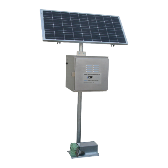
Installation Instructions
The iCIP
™
(Intelligent Chemical Injection Pump) assembly
comes with connections which are provided to protect
against accidental electrical shock. There are connectors
inline provided for both the battery(s) and the solar panel(s).
The connectors should not be connected while the iCIP
being assembled or during any maintenance period.
Solar Panel (+ White)
Solar Panel (- Black)
Figure 2– Solar Panel and Battery Connections
A 2.0 inch Diameter Schedule 40 Galvanized coated 6 foot
mounting pole has been provided for attaching both the
Solar Panels and Battery Enclosure. The pole can be firmly
attached to a leg of a solutions tank rack. An alternative
method for securing the mounting pole would be to drive a
T-Post into the ground, slip the pole over the T-Post and add
a generous amount of Quick-Set concrete to the top opening
of the pipe.
U-bolts have been included to secure the battery enclosure
to the mounting pole. The distance from the ground to the
underside of the enclosure should be approximately 36
inches. This will allow the operator to sit comfortably on a
stool while making input changes to the Motor Controller
or to isolate the solar panel and battery power supplies for
routine maintenance. Avoid over tightening of the U-bolt
nuts to prevent damage to the battery enclosure.
For Safety purposes, the battery and solar panels should
not be connected until all other assembly steps have been
completed.
Solar Panel Mounting
Mounting hardware to attach the solar panels to the pole has
been pre-assembled to aid in field installation. Prior to
placement of the 3-Outlet 2.0 inch Diameter Pipe Tee, loosen
the Azimuth (direction the solar panels face) Adjustment set
screw. Reference Figure 3. Position the bottom inlet on top
of the pole, making sure it is firmly centered and seated
down. Make sure that there aren't any shadows that could
contact any portion of the solar panel.
™
is
Solar Converter (+ White)
Solar Converter (- Black)
Tilt Locking Set-Screws
Figure 3
Solar Panel Alignment
During "sun hours" the solar panels are used to recharge the
battery voltage used during the night or non sun hours. The
solar mounting assembly should be adjusted to achieve
Maximum Effective Irradiance or Maximum Peak Power
(maximum sun hours). Configuring the azimuth (direction
the solar panels face) and horizontal (tilt) placement of the
Solar Panels is critical and should be adjusted or aligned at
midday to achieve maximum "sun hours".
To adjust both the direction the solar panels face and the
tilt positions on the Solar Panel Mounting. There are (3)
5/8 in.- Set Screws on the 3-outlet 2.0 in. diameter pipe tee
component of the mounting assembly, which will require a
5/16 Allen Wrench. Reference Figures 3 and 4.
STEP 1: Direction: Adjust the Solar Panel Array azimuth
(direction the solar panels face) by facing the assembly
towards true South, not magnetic south. True South (Solar
Noon) is defined as the position halfway between Sunrise
and Sunset. Determine the halfway point between sunrise
and sunset for a given day, and face the solar panels in that
direction.
STEP 2: Tilt: Dresser recommends the tilt angle be set for
winter or the winter solstice (December 21). Use one of the
following methods to set the tilt of the solar panels.
Method 1: Reference Figure 6 to obtain the desired Tilt angle
with respect to the Latitude of the end customer's well
location on the Right side of the graph. Follow the curve
across the graph to the Left side to "Photovoltaic Module
Angle" (Degrees) with reference to the horizontal plane.
Use a cheap protractor, and a foot long piece of string
with a small weight attached to the end to set the tilt of the
solar panels.
2
Azimuth Locking Set-Screw