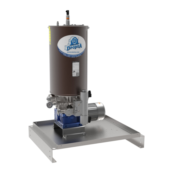
DROPSA SUMO II Series Посібник з експлуатації та обслуговування - Сторінка 7
Переглянути онлайн або завантажити pdf Посібник з експлуатації та обслуговування для Водяний насос DROPSA SUMO II Series. DROPSA SUMO II Series 13 сторінок.

7.3
ADJUSTMENT/ CALIBRATION OF LEVEL PROBES
7.3.1 LASER PROBE SETTING 0295131, 24V cc Out NO and NC (1 threshold)
* To obtain a correct setting bring the lock ring to maximum setting value and then down to desire value.
On the pump is placed a label that shows the wiring diagram and setting values. The pump is normally equipped with pre setting
sensor to "L" thresholds (minimum level). Whereas other thresholds: MM (absolute maximum level), M (absolute level), LL
(absolute minimum level), can be set
Attention you can only set one thresholds at a time
7.3.3 Procedure for calibrating the laser probe 24V cc Out 4÷20mA/2 NO (4 thresholds)
The laser probe possesses a representative and programming display mounted on board. It is possible to operate in analogue
mode (with signal from 4 to 20 mA) or in digital mode (two outputs and four intervention thresholds).
We attach a table showing the calibration parameters for the laser probe.
Image 6
NOTE: To change calibration thresholds of laser and ultrasound probes contact DROPSA staff
7.3.4 Collegamento galleggiante REED 0295150/0295160
Pos.
Level
Output
signal
A
Maximum
absolute level
OUT 2= Fno
C
Minimum level
B
Maximum level
D
Minimum
OUT 1= Fno
absolute level
1.
Reference notch
2.
Yellow led: lights when the set value is reached, (outlet=ON).
3.
Lock ring
4.
Setting lock ring (be adjusted manually after unlocking).
5.
Green led: indicates the correct power supply (24V cc).
LASER PROBE CALIBRATION
100 kg reservoir
set-up
height X
[mm]
nsP2
220
fsP2
300
nsP1
250
fsP1
330
30 kg reservoir
Quantity of
height X
Quantity of
grease [kg]
[mm]
grease [kg]
90
220
17
490
86
250
14
520
23
5
21
3
