Daikin R32 Split Series Посібник з монтажу - Сторінка 9

Переглянути онлайн або завантажити pdf Посібник з монтажу для Вентилятор Daikin R32 Split Series. Daikin R32 Split Series 16 сторінок. R32 split series
Також для Daikin R32 Split Series: Посібник з монтажу (17 сторінок), Посібник з монтажу (16 сторінок), Посібник з монтажу (16 сторінок), Посібник з монтажу (16 сторінок), Посібник з монтажу (17 сторінок), Посібник з монтажу (16 сторінок), Посібник з монтажу (20 сторінок), Посібник з монтажу (14 сторінок), Посібник з монтажу (14 сторінок), Посібник з експлуатації (16 сторінок), Посібник з експлуатації (16 сторінок), Посібник з експлуатації (8 сторінок), Посібник з монтажу (17 сторінок), Посібник з монтажу (16 сторінок), Посібник з монтажу (20 сторінок), Посібник з монтажу (20 сторінок), Посібник з монтажу (16 сторінок), Посібник з монтажу (16 сторінок), Посібник з монтажу (14 сторінок), Посібник з монтажу (14 сторінок), Посібник з монтажу (17 сторінок), Посібник з монтажу (20 сторінок), Посібник з монтажу (13 сторінок)
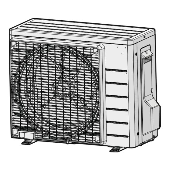
Daikin R32 Split Series Посібник з монтажу
4.

Wiring

Refer to the installation manual for the outdoor unit also.
WARNING
• Do not use tapped wires, extension cords, or starburst connections, as they may cause overheating, electric shock, or fire.
• Do not use locally purchased electrical parts inside the product. (Do not branch the power for the drain pump, etc., from the
terminal block.) Doing so may cause electric shock or fire.
• Do not connect the power wire to the indoor unit. Doing so may cause electric shock or fire.
CAUTION
Recommend stranded cable for interunit wiring. Local code always supersedes recommendation.
• For stranded wires, make sure to use the round crimp-style terminal for
connection to the power supply terminal block. Place the round crimp-
style terminals on the wires up to the covered part and secure in place.
Flat washer
Screw
• If solid core wire must be used, be sure to curl the end of the lead.
Improper work may cause heat and fire.
1) Remove the front grille. (Refer to "2. Removing and installing
the front grille" on page 11.)
2) Remove the conduit mounting plate and then secure the
conduit to the conduit mounting plate with the lock nut, as
shown in the illustration.
3) Strip wire ends (3/4 inch (20mm)).
4) Match wire colors with terminal numbers on the indoor and
outdoor unit's terminal blocks and firmly secure the wires in the
corresponding terminals with the screws.
5) Connect the ground wires to the corresponding terminals.
6) Pull the wires lightly to make sure they are securely connected.
7) In case of connecting to an adapter system, run the remote
controller cable and attach the S21.
(Refer to "4. When connecting to an HA system" on page 12.)
8) Attach the conduit mounting plate.
9) Shape the wires so that the service lid fits securely.
10) Attach the front grille. (Refer to "2. Removing and installing the front
grille" on page 11.)
11) Take care to ensure that all wiring between the indoor unit and the outdoor unit
has a consistent connection. Any splices can cause communication errors.
English
A
Round
crimp-style
Good
terminal
Round crimp-style
terminal
Screw
Round crimp-style
terminal
Flat washer
Wrong
Arrow view A
Good
Strip wire ends
3/4 inch
(3/4 inch
(20mm)
(20mm)).
Firmly fix the wires with the terminal screws.
Using AWG14 (09/12 class), AWG12 (18/24
class), stranded and insulated wire for
connections between indoor and outdoor
units is recommended. Local codes always
supersede recommendations.
1
Indoor
2
3
unit
Stranded wire
Screw
Flat washer
Round crimp-style
terminal
Wrong
Terminal block
Electrical wiring box
Wire retainer
Shape wires so that
the service lid fits
securely.
Use the specified wire type.
Lock nut
Back
Conduit
mounting plate
Conduit
Seat the claw
onto this part
Claw
and secure
Outdoor
unit
1 2 3
L
L
1
2
Firmly fix the wires with the terminal screws.
8