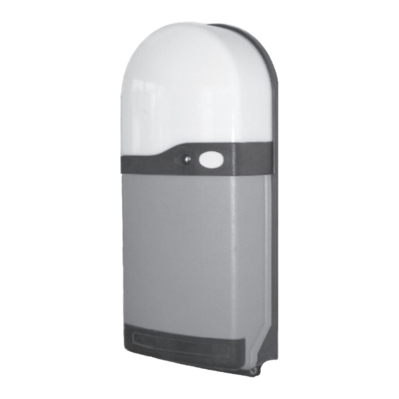
Ansa RS-1 Посібник з монтажу та експлуатації - Сторінка 4
Переглянути онлайн або завантажити pdf Посібник з монтажу та експлуатації для Блок управління Ansa RS-1. Ansa RS-1 12 сторінок. Ansa roller door remote control unit

- 1. Table of Contents
- 2. General Description
- 3. General Operation
- 4. Multi Channel Keyfobs
- 5. Fitting the RS-1 Control Unit
- 6. Electrical Connections
- 7. Photoelectric Cell Safety System (Optional)
- 8. Light Grid Safety System (Optional)
- 9. Alarm System (Optional)
- 9. Figure 16
- 9. Commissioning
- 9. Adding/Deleting Transmitters & Wireless Access Controls
- 9. Dip Switch Options & Special Settings
- 9. Technical Specifications
4
Electrical Connections
Always switch off the mains power supply before making any connections!. Electrical connections should be carried out by
a competent person. If in doubt consult a qualified electrician! Cables should enter the control unit through the cable
glands fitted to the bottom of the RS1 unit.
4.1 Power
The 240v A/C input should be connected from an adjacent 13 amp 3 pin switched socket. The plug must be fitted with a 5 amp
fuse. Connect to terminals marked MAINS, N, L,
4.2 Motor
Connect the motor lead to the terminals marked
the terminal marked N3. Connect the yellow/green earth cable to the terminal marked E. Connect the brown and black motor
power cables to terminals L1 & L2. Ensure that motor direction matches the open and close LEDs if necessary interchange the
motor cables at terminals L1 & L2 (See figure 9).
4.3 Adding Lighting
Terminals marked LIGHT, E, L, N, provide a 240 volt ac lighting output which functions the same as the built on light. Lighting
switches on for 4 minutes whenever the door is operated and turns off automatically. Maximum load 400 watts.
4.4 Connecting a Photoelectric Cell System (optional)
Remove the factory fitted link connecting 0V and Sig.
Connect the blue wire to
·
Connect the black wire to
·
Connect the brown wire to
·
4.5 Connecting The LG-1 Light Grid System (optional)
Remove the factory fitted link connecting 0V and Sig.
Connect both the blue wires to
·
Connect both the black wires to
·
Connect both white wires to
·
Connect both brown wires to
·
4.6
Connecting a Push Button (Hard Wired)
A push to make (normally open) push button or key switch can be connected to terminals COM & IMP ,.
This provides an OPEN - STOP - CLOSE - STOP sequential operation which works the same as the keyfob.
4.6 Connecting a Stop Push Button (Hard Wired)
A push to break (normally closed) push button or key switch can be connected to terminals marked COM & STP .
Activation will stop the door immediately regardless of it's position. If used remove the factory fitted link connecting COM & STP .
4.7 Fitting the Aerial. An external aerial is supplied which must be fitted as follows:
Pass the 135mm stainless steel wire aerial through the small hole in the base of the RS1 control unit alongside the right hand cable
entry and connect to the terminal marked "EXT A". It is also possible to fit a 'remote' aerial. Connect via coax cable with the
inner wire core connected to terminal "EXT A". Separate the screen from the wire core and connect to terminal "SC", and strip
off 135mm of the screen at the free end.
4.8 Fitting the optional ANSA Alarm System (Type AL12/HW)
Fix the alarm module alongside the left hand side of the RS1 Unit. Pass the connection lead through the right hand cable entry
gland and connect the plug to the security alarm socket on the RS1 circuit board (see fig 8).
Connect the alarm trip switch cables to terminals AL1 and AL2. The trip switch is fitted to the bottom of the door guide and a
magnet is fitted to the bottom door slat to trigger the system in the event of a break in attempt.
Note:
The alarm unit has two volt-free normally closed terminals which can be optionally connected directly to the home
alarm system.
Page 3
MOTOR,
E, L1, L2, N3. The blue motor neutral cable must be connected to
0V
Sig
24V
(Connections are for the ANSA PEC-3 Photocell Unit)
0V
Sig
Test
24V
