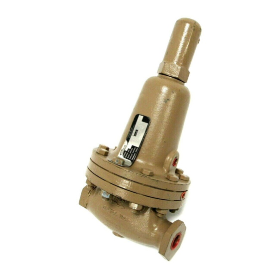
cashco 1000HP-5 Інструкція з монтажу, експлуатації та технічного обслуговування - Сторінка 2
Переглянути онлайн або завантажити pdf Інструкція з монтажу, експлуатації та технічного обслуговування для Контролер cashco 1000HP-5. cashco 1000HP-5 14 сторінок. Cryogenic pressure reducing regulator

7. In placing thread sealant on pipe ends prior to
en gage ment, ensure that excess material is
removed and not allowed to enter the regulator
upon startup.
8. Flow Direction:
match es the arrow cast on the body.
9. For best performance, install in well drained
hor i zon tal pipe. Recommended position is with
spring chamber vertically downwards. Orient
to prevent the spring cham ber vent hole from
collecting rainwater or debris, and so drain hole
III. PRINCIPLE OF OPERATION
1. The Model 1000 is available in two vari a tions:
1000LP (larger diaphragm) for down stream pres-
sure control from 1-30 psig; 1000HP (small er
diaphragm) for down stream pressure control from
10-300 psig, body size dependent.
2. Movement occurs as pressure variations reg-
ister on the diaphragm. The registering pres sure
is the outlet, P
range spring opposes di a phragm move ment. As
outlet pressure drops, the range spring pushes
the diaph ragm up, opening the port; as outlet
pressure increases, the dia phragm push es down
and the port closes.
3. The Model 1000 includes a rocker arm in its
op er a tion al mechanism. The rocker arm allows
the regulator to operate flow-to-open (FTO),
rather than conventional flow-to-close (FTC),
which increases rangeability.
4. Due to the FTO design, there is a limit as to how
low of a downstream (P
setting is capable for a given inlet P
2
Install so the flow direction
, or downstream pressure. The
2
or outlet) pressure level
2
pressure.
1
can drip melted condensate as re quired. A purge
gas is recommended for the spring cham ber.
10. Regulators are not to be direct buried under-
ground.
11. For insulated piping systems, recommen dation is
to not insulate regulator.
12. Cashco does not recommend field welding on
the cyl in der (inlet) end of the regulator, due to the
possibility of warpage.
SECTION III
This is a function of the ratio of the port area to
di a phragm area. It is possible for there to be too
high of an inlet pressure for the regulator to close
off against. (Refer to Technical Bulletin, Tables 6
and 7 for limits.) Reduced port, Option -12 allows
low er down stream (P
for a given up stream (P
5. The FTO design also is limited by a minimum
pressure drop. If the regulator pressure drop is
below 5 psi, an Option 1000-17 Piston Spring
should be utilized to assist open ing the valve
piston. (Standard with 1000-5; must be speci fied
with 1000-36.)
6. The Model 1000 includes an aspiration jet ef fect,
due to the clearance of the piston from the body
near the regulator's outlet. These clear ances vary
as to whether the fluid is a gas or a liquid. Jets must
be se lec ted to match one of these two general
fluids. An improper jet selection will reduce perfor-
mance.
7. A complete diaphragm failure will cause the
regulator to fail open.
or outlet) pressure set tings
2
or inlet) pressure level.
1
IOM-1000HP-Cryogenic
