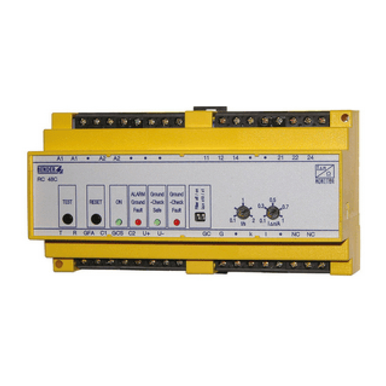
Bender RC48N Посібник - Сторінка 3
Переглянути онлайн або завантажити pdf Посібник для Монітор Bender RC48N. Bender RC48N 8 сторінок. Ground-fault neutral-grounding monitor
Також для Bender RC48N: Посібник (12 сторінок)

6
DIP-Schalter:
Filter off / on: Bandpassfilter 50 ... 60 Hz
Ist der Bandpassfilter eingeschaltet, werden ausschließ-
lich die 50 ... 60 Hz-Komponenten des Differenzstromes
schmalbandig erfasst. Diese Funktion kann verwendet
werden, um Fehlauslösungen durch harmonische und
transiente Komponenten im Differenzstrom zu vermei-
den.
Δ
I
n x 10 / x 1: Einstellbereich für den Ansprechwert des
Differenzstroms I
Δ
n/A einstellen:
x 1
0,1 A ... 1 A
x 10
1 A ... 10 A.
7
Ansprechverzögerung t/s für Differenzstrommessung im
Bereich von 0,1 ... 2 Sekunden einstellen.
8
Ansprechwert des Differenzstroms im Bereich von
0,1 A ... 1 A bzw. 1 A ... 10 A einstellen.
9
Ansprechwert für Spannungsabfall am Erdungswider-
stand im Bereich von 20 ... 400 V einstellen.
Einbau
Das Gerät ist für folgende Einbauarten geeignet:
• Installationsverteiler nach DIN 43 871 oder
• Schnellmontage auf Hutprofilschiene (A) nach DIN EN 50022
• oder Schraubmontage (B).
Stellen Sie vor Einbau des Gerätes und vor Arbeiten
an den Anschlüssen des Gerätes sicher, dass die Anla-
ge spannungsfrei ist.
Wird dies nicht beachtet, so besteht für das Personal
die Gefahr eines elektrischen Schlages.
Außerdem drohen Sachschäden an der elektrischen
Anlage und die Zerstörung des Gerätes.
Beachten Sie das Anzugsdrehmoment für die Klemmschrauben
der Anschlüsse (C): 0,5 ... 0,6 Nm (4,3 ... 5,3 lb-in).
Abb. 1: Maßbild RC48N,
alle Maße in mm (inch)
TBP401013deen / 05.2008
6
DIP switch:
Filter off / on: bandpass filter 50 ... 60 Hz
When the bandpass filter is switched on, only the narrow-
band 50 ... 60 Hz components of the residual current are
detected. This function can be used to avoid false trip-
pings caused by the occurrence of harmonics and transi-
ent components in the residual current.
Δ
I
value I
x 1
x 10
7
For setting the maximum time delay t/s for the residual
current measurement from 0.1 to 2 seconds.
8
Setting the residual current response value to 0.1 A ... 1 A
respectively 1 A ... 10 A.
9
Setting of the response value for voltages across the neu-
tral grounding resistor from 20 to 400 V.
Installation
The device is suited for:
• mounting into standard distribution panels acc. to DIN 43 871
• or DIN rail mounting (A) acc. to DIN EN 50022
• or screw mounting (B).
Terminal screw torques is as follows:
(C): 0.5 ... 0.6 NM (4.3 ... 5.3 lb-in).
In Australia contact Captech.com.au
Phone 1300 280 010
n x 10 / x 1: for setting the residual current response
Δ
n/A:
0.1 A ... 1 A
1 A ... 10 A.
Prior to installation and before work activities are
carried out on the connecting cables, make sure that
the mains power is disconnected.
Failure to comply with this safety information may
cause electric shock to personnel.
Furthermore, substantial damage to the electrical in-
stallation and destruction of the device might occur.
Dimension diagram RC48N,
all dimensions in mm (inch)
RC48N
3
