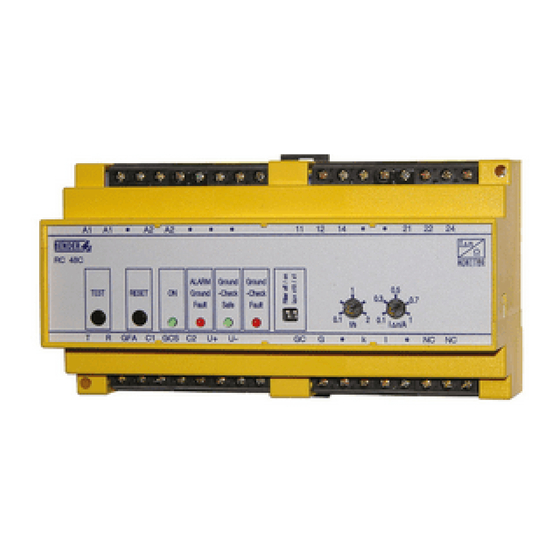
Bender RC48N Посібник - Сторінка 4
Переглянути онлайн або завантажити pdf Посібник для Монітор Bender RC48N. Bender RC48N 8 сторінок. Ground-fault neutral-grounding monitor
Також для Bender RC48N: Посібник (12 сторінок)

RC48N
Anschluss
Schließen Sie das RC48N wie im folgenden Anschlussbild be-
schrieben an.
Legende zum Anschlussbild
Geräte:
CD...
Ankoppelgerät CD1000 oder CD5000 ermöglicht das
Messen der Spannung zwischen Sternpunkt des Transfor-
mators und Erde. Ordnen Sie das Ankoppelgerät CD.. in
der Nähe des Erdungswiderstandes an.
CT
Differenzstromwandler zur Erfassung des über den Er-
dungswiderstand NGR fließenden Stroms. Positionieren
Sie den Differenzstromwandler wie im Anschlussbild dar-
gestellt. Falls ein Isolationsfehler im Erdungswiderstand
NGR ausgeschlossen werden kann, so kann der Differenz-
stromwandler auch zwischen Erdungswiderstand und
Erde angeordnet werden. Schließen Sie den Wandler an
die Klemmen k und l des RC48N an.
Keiner der Wandleranschlüsse darf geerdet werden.
Ein Überspannungsschutz ist im Wandler integriert.
K1
Externer Leistungsschalter schaltet überwachtes System
im Falle eines Alarms ab.
NGR
Erdungswiderstand (Neutral grounding resistor).
RI2000NC
Melde- und Prüfkombination (Option) mit Test-Taste
(T), Reset-Taste (R), LED „ALARM Ground Fault" (GFA) und
LED „ALARM Resistor Fault" (NRA). Die Funktionen der
Tasten und LEDs entsprechen denen der gleichnamigen
Bedienelementen am RC48N.
F
Kurzschlussschutz Speisespannung. Empfehlung: 6 A Si-
cherung
4
Connection
Connect the RC48N as shown in the diagram below.
Legend to wiring diagram
Components:
CD...
Coupling devices CD1000 or CD5000 allow for voltage
measurement across the neutral grounding resistor.
Install the coupling device CD.. near the neutral groun-
ding resistor.
CT
Residual current transformers to detect the current
flowing through the neutral grounding resistor.
Place the residual current transformer as shown in the wi-
ring diagram. The residual current transformer can also
be placed between the neutral grounding resistor and
ground provided that no insulation fault exists in the neu-
tral grounding resistor. Connect the residual current
transformer to the terminals k and L on the RC48N.
None of the CT connections must be grounded.
The residual current transformer is equipped with an
overvoltage protection.
K1
External load switch, disconnects the system being moni-
tored in case of an alarm.
NGR
Neutral grounding resistor
RI2000NC Remote alarm indicator and operator panel with TEST
button (T), RESET button (R), "Alarm Ground Fault" LED
(GFA) and "Alarm Resistor Fault" LED (NRA). The functions
of the buttons and LEDs and the designations correspond
to the respective operating elements on the RC48N.
F
Short-circuit protection supply voltage: a 6 A fuse is re-
commended.
In Australia contact Captech.com.au
Phone 1300 280 010
TBP401013deen / 05.2008
