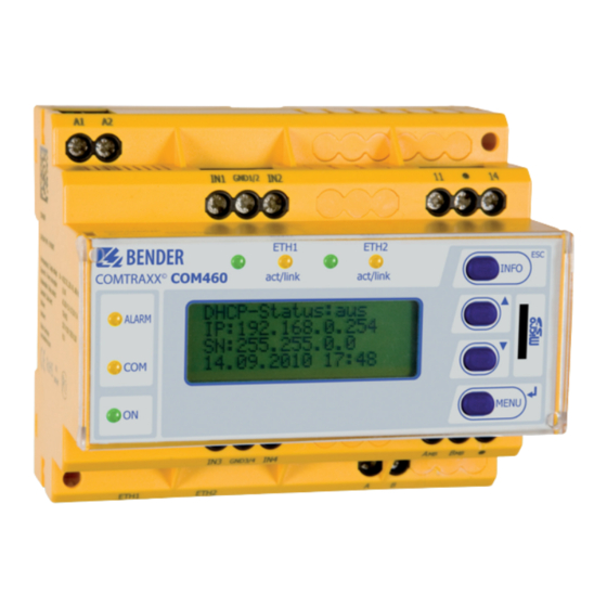
Bender COMTRAXX COM460IP Короткий довідник - Сторінка 3
Переглянути онлайн або завантажити pdf Короткий довідник для Шлюз Bender COMTRAXX COM460IP. Bender COMTRAXX COM460IP 4 сторінки. Bms-ethernet-gateway for the connection of the bender measuring device interface to tcp/ip networks

Quick reference guide "Installation and connection"
COMTRAXX® COM460IP
BMS-Ethernet-Gateway for the connection of the Bender measuring device interface to TCP/IP networks
This quick start does not replace the manual. The manual can be found on the web user interface ("Tools" > "Manual") or in the download area of
our homepage. Make sure that the personnel has read this manual and understood all instructions relating to safety.
1. Safety instructions
Danger: Risk of fatal injury from electric shock
Parts of the system are live. During installation and connection:
►
Do not touch parts of the system.
►
Disconnect the system from the power supply and protect the
system against accidental switch-on.
Warning: Place of installation
Choose a place of installation where only authorised individuals have
access to the device. This can be a switchboard cabinet, for example.
2. Scope of delivery
• The COM460IP
• An manual as a PDF file in the device memory
• This quick quick start
4. Connection of the device
Wiring diagram
U
S
A1 A2
6 A
6 A
A1
A2
ETH1
Web-
Browser
LAN
For UL application, please observe:
– Supply voltage U
see nameplate and ordering information
S
Maximum ambient temperature 55°C
For use in pollution degree 2 environments
Only 60/75 °C copper wires are to be used
Tightening torque for terminals 0.5...0.6 Nm
Connection
1.
Connect the device according to the wiring diagram. Connect
the gateway to the LAN provided for this gateway. Check that
the connection is correct.
2.
Check that the supply voltage applied corresponds to the
value printed on the nameplate of the COM460IP.
COM460IP_D00023_02_Q_DEEN/01.2016
GND
IN1
IN2
11
14
1/2
GND
IN3
IN4
AMB
BMB
3/4
A B
ETH2
BMS-Bus
RJ45
RS-485
Warning: Risk of destruction if mains voltage incorrect
►
Ensure that the mains voltage matches the value printed on the
nameplate.
Warning: Malfunction due to double address assignment
Assigning addresses that are already used by existing devices in the
BMS or TCP/IP networks concerned may cause serious malfunctions.
Note: Do not remove the Micro-SD card
Do not remove the Micro-SD card to ensure that all device features are
retained!
3. Installing the device
Mounting possibilities:
• DIN rail mounting
• Screw mounting with 2 x M4
Terminal
A1, A2
IN1,
GND1/2, IN2
11, 14
(AMB, BMB)
IN3,
GND3/4, IN4
AMB, BMB
Ron/off
(AMB,BMB)
ETH1, ETH2
A, B
Ron/off
(A,B)
Description
Connection to the supply voltage, 6 A fuse rec-
ommended, IT systems require two fuses.
For UL and CSA applications, it is mandatory to
use 5 A fuses
Currently has no function (digital inputs)
Currently has no function (alarm relay K1)
Currently has no function (digital inputs)
Currently has no function
Currently has no function
Two connections for connection to a personal
computer or connection to the local network
(Hub, Switch, Router); Connection with a CAT5
cable; internal Layer-2-Switch with cable auto-
detect
Connection to internal BMS bus with cable
twisted pair, shielded, shield connected to PE on
one side (recommended: J-Y(St)Y min. 2 x 0.8)
Switch for BMS bus termination. When the device
is installed at the end of the bus, set the terminat-
ing switch to "on"
EN-1
