Benedini TBS Mini V2 Посібник - Сторінка 5
Переглянути онлайн або завантажити pdf Посібник для Обладнання для запису Benedini TBS Mini V2. Benedini TBS Mini V2 13 сторінок. Digital multifunctional rc-soundmodule
Також для Benedini TBS Mini V2: Посібник з експлуатації (7 сторінок)
Remote volume control
If "Encoder" or "Indirect sound selection" control mode is used, the volume can be set remotely
from the transmitter (If the TBS Mini parameters are set accordingly!)
Standard setting:
Function Nr. 11: Volume up
Nr. 12: Volume down
Operation:
Select the desired function and KEEP it triggered → Volume changes constantly
If the desired volume is reached, release the trigger button.
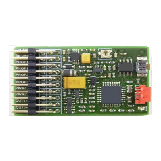
Speaker:
If the speaker is connected by a common servo cable, use the
ORANGE
(+ speaker)
and
RED
(- speaker) lead. Brown is not used.
4 or 8 ohm speakers can be used. Make sure not using the amplifier connector of the TBS Mini !
Prop 1 (Receiver speed channel)
Prop1 is available twice, both are identical. The receiver speed channel is connected to one of them,
the ESC can be connected to the second one.
Note:
If a ESC with integrated BEC is used for powering the receiver, it is highly recommended using a
separate servo y-cable for connecting the receiver speed channel to the ESC and Prop1 of the TBS
Mini. This ensures that the receiver supply current (coming from the ESC) flows directly to the
receiver and not through the sound unit.
Prop2 (optional)
This multi functional receiver input can be configured to the following:
- Second speed channel input for tracked models
- Control input for selecting the desired sound to play
- Sensor input for load dependant sound adjustment
→ Please see details on the TBS Flash manual.
Prop3
Receiver input for selecting the desired sound to play.
PWM 1
Servo1 signal or switching output (Out10)
→ Please see details on the TBS Flash manual.
PWM 2
Servo2 signal or switching output (Out11)
→ Please see details on the TBS Flash manual.
Out 1-4
Universal switching outputs
Hints to switching outputs Out 1-4, Out 10 and Out 11
The desired outputs must be configured by the TBS Flash software according to the desired
functionality (switching, momentary, flashing). This can be done by the TBS Flash software and the
optional USB programming cable.
!! All outputs are switching to NEGATIVE of the receiver supply voltage !!
PLUS is available at the centre contacts of each connector → See connection picture above.
Out 10 is located at the signal pin of PWM1 (upper pin)
Out 11 is located at the signal pin of PWM2 (upper pin)
TBS Mini V2, 11/2018
www.benedini.de
Page 5 of 13