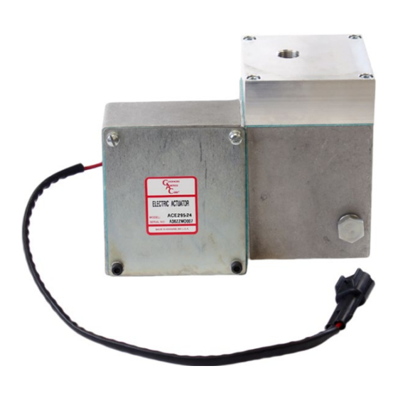
GAC ACE295 Series Короткий посібник - Сторінка 2
Переглянути онлайн або завантажити pdf Короткий посібник для Контролер GAC ACE295 Series. GAC ACE295 Series 4 сторінки. Integrated pump mounted electric actuator

3
INSTALLATION DIAGRAM
4
INSTALLATION
An overspeed shutdown device, independent of the governor system, should be used to prevent loss of engine control which
may cause personal injury or equipment damage. Do not rely exclusively on the governor system electric actuator to prevent
overspeed. A secondary shutoff device, such as a fuel solenoid must be used.
PREPARING THE FUEL PUMP
If the pump is equipped with a mechanical governor, it must be removed. GAC recommends that the modification be done
by a qualified fuel injection shop.
The following are general instructions for removing the existing governor and should not be used without a qualified professional.
NOTE
Oil must be removed from the mechanical governor.
1.
Remove the rear housing of the existing mechanical governor and disconnect the governor assembly from the fuel rack.
2.
Remove the flyweight assembly.
3.
Remove the intermediate governor housing, this leaves only the rack and camshaft protruding from the housing.
4.
Remove the oil hex plug located on the pump between the fuel rack and the camshaft to allow any oil which leaks from the fuel rack to
drain back into the pump.
CONNECTING ACTUATOR LINKAGE TO FUEL RACK
1.
Remove the four cap screws and carefully remove the gasket from the
cover on the actuator to access the lever assembly used to connect the
actuator to the fuel rack. Save the screws and gasket.
2.
Remove the set screw from the bracket. DO NOT LOOSEN LEVER OR
REMOVE LEVER FROM THE SHAFT.
2
Governors America Corp. © 2020 Copyright All Rights Reserved
NOTE:
Dimensions shown are nominal.
Final dimensions may vary slightly.
ACTUATOR lEVER
ASSEMBlY
ACE295 Series Actuator 3-2020-C
Units
[
]
[mm]
X.X
X.X
in
PIB4160
