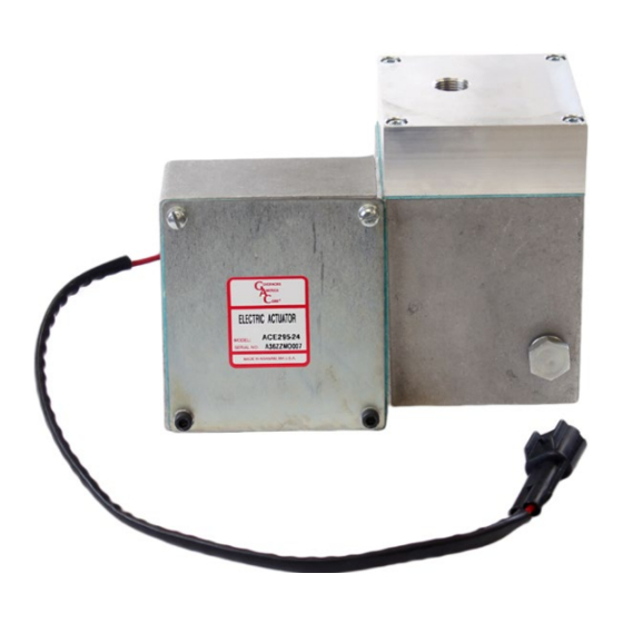
GAC ACE295 Series Короткий посібник - Сторінка 3
Переглянути онлайн або завантажити pdf Короткий посібник для Контролер GAC ACE295 Series. GAC ACE295 Series 4 сторінки. Integrated pump mounted electric actuator

4
INSTALLATION (CONTINUED)
3.
From the KT295 kit, select the P9 (15 mm) or P10 (14 mm) fuel rack adapter and
the socket head screw. Align the fuel rack adapter over the connecting screw
hole of the fuel control rack. Apply loctite Thread Retention Compound to the
socket head screw. Using the socket head screw, connect adapter to fuel control
rack and torque to 7.8 - 8.4 N∙m (5.8 - 6.2 lbf∙ft).
4.
Connect the linkage extension from kit KT295 to the end of the fuel rack adapter
using the M5-16 hex-head screw and washer, and torque to 4.6 - 5.1 N∙m (3.4 -
3.8 lbf∙ft).
The linkage is preset to a specific length and locked. Any adjustment
NOTE
of rack travel must be made using the slot on the actuator lever. This
is completed after the actuator is mounted to the fuel pump.
5.
Attach the actuator to the pump by first cleaning the mounting surfaces of the
actuator and the pump. Remove the gasket and screws from kit KT296. The
gasket fits between the actuator and pump.
6.
Apply a small amount of high temperature gasket sealant, such as RTV silicone,
to the pump side of the gasket. Align the gasket on the pump side to get the most
complete coverage.
7.
Place the rear mounting side of actuator over the pump rack and linkage on the
bearing retainer plate. Attach the actuator to the pump using two of the four
screws and washers included with KT295, through the upper mounting holes.
Tighten screws securely to 9 N∙m (6.6 lbf∙ft) taking care to compress the gasket
evenly.
8.
Push the lower mounting bar against the bearing retainer plate and tighten the
two bottom nuts onto the pump studs to 10 N∙m (7.3 lbf∙ft).
Make sure the linkage attached to the fuel rack moves freely when
NOTE
moved from shut off to full fuel.
9.
If necessary for access, loosen the two hex nuts that hold the front set screw
bracket to gain access to the lever area.
10. Pull the linkage fully away from the pump. Push the linkage 1 mm toward the
pump and attach it to the slot on the actuator lever using the M5x20 screw, two
flat washers and the locking nut from kit KT295. Torque the lock nut to 4.6 - 5.1
N∙m (3.4 - 3.8 lbf∙ft).
11. The fuel rack should be 1 mm or less away from its internal physical stop. The
zero fuel stop of the system will now be provided by the actuator instead of inside
the fuel pump.
12. Manually move the actuator lever and linkage through its full range of motion. No
binding should be noticed. The stop plate on the linkage must not contact the
inside of the housing.
13. If loosened for access, torque the two screws holding the mounting bar to the
actuator to 20 N∙m.
14. Use the set screw and nut on the set screw bracket to adjust the maximum fuel
position on the actuator lever. The set screw and lock nut is adjusted to limit the
travel of the fuel rack.
15. After the maximum fuel delivery has been adjusted reinstall the saved gasket,
four cap screws and cover.
16. Access the set screw as required through the actuator cover.
KT295 CONTENTS
KT296 CONTENTS
3
Governors America Corp. © 2020 Copyright All Rights Reserved
SET SCREW
ACE295 Series Actuator 3-2020-C
PIB4160
