2gig Technologies Vario Посібник зі швидкого встановлення - Сторінка 5
Переглянути онлайн або завантажити pdf Посібник зі швидкого встановлення для Система безпеки 2gig Technologies Vario. 2gig Technologies Vario 18 сторінок. Voice module
Також для 2gig Technologies Vario: Інструкція з монтажу Посібник з монтажу (6 сторінок), Короткий посібник користувача (10 сторінок)
2GIG Vario Quick Install Guide
Notes:
The parallel wiring system supports parallel connections from any point along the wiring.
The maximum wire run permitted is 300 meters (1000 feet) for all legs of the BUS.
In case of BUS communication problems, connect two 2.2KΩ resistors—one at each end of the data BUS terminals, between the green and
yellow wires.
If connecting remote power supplies, DO NOT connect the red wire (+12V) between the power supply unit and the 2GIG Vario
system.
For long cable runs, use the correct cable, as listed in "Appendix C: Wiring" in the 2GIG Vario System Installation & Programming Guide.
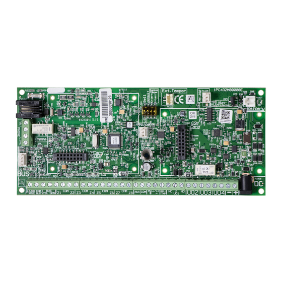
1. Set BUS Accessory ID Numbers
For most devices, a DIP switch number must be set to identify its ID category number. Devices are split into "Families." Each "Family" of devices has
sequential identification numbers which are set by the DIP switches. Before setting power on, define each module's ID number by setting the DIP switches
as follows:
Notes:
Most accessories have four DIP switches, while BUS detectors have five DIP switches.
IDs 9–32 are only available for BUS detectors.
If a DIP switch is changed on any device, it is necessary to shut down the dvice's power and then re-power it.
The first module in each category is defined as ID = 1.
Families that have sequential ID numbers are:
Keypads
Zone expanders
Outputs
Power supplies
BUS zones
Wireless zone expanders
Notes:
The main unit can support a maximum load of 1.4 Amp. If more current is required, install additional power supply modules (3 Amp max.).
On 3 Amp supervised power supplies and on the wireless expander, there are two programmable outputs. These programmable outputs belong
Copyright © 2016 Nortek Security & Control LLC
5