GAI-Tronics 262-001 Інструкція з експлуатації - Сторінка 3
Переглянути онлайн або завантажити pdf Інструкція з експлуатації для Телефон GAI-Tronics 262-001. GAI-Tronics 262-001 16 сторінок. Intrinsically safe telephone
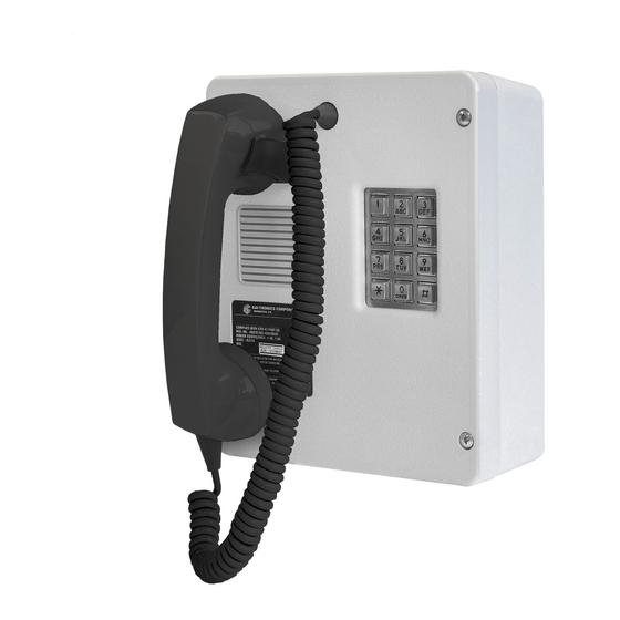
Model 262-001 and 272-001 Intrinsically-Safe Telephones
Wiring Requirements
Design Limits
In order to be intrinsically safe, energy and energy storage must be constrained to "safe" levels in
hazardous area apparatus. Wiring inherently has capacitance formed by a dielectric material between two
conductors. A buildup of this capacitance can form a surge of electricity, a dangerous situation in a
hazardous area.
Intrinsically-safe telephones require cabling that will limit the amount of capacitance formed. The
limitation on cable length was set by Underwriter's Laboratory (UL) based on test results. This "worst
case" cable available was found to have a capacitance of 60 picofarads/foot. Therefore, UL set the cable
limitation at one mile, the length at which this worst-case cable capacitance level was still within
acceptable bounds. Cable types with less capacitance have been specified to allow connection distances
over one mile.
For example: GAI-Tronics Model 60059-001 and 60021-301 cables allow connection distances of up to
1.5 miles.
Shielded Cable
Where multiple intrinsically-safe telephone wires are routed together, shielded cable should be used. The
use of shielded cable prevents cross-talk from occurring between multiple intrinsically-safe telephone
circuits. The shield must be grounded to an intrinsically-safe ground and connected only at the IBU.
Wiring Guidelines/Control Drawing
The Model 262-001 and 272-001 I.S. Telephones must be installed in accordance with GAI-Tronics
control drawing 73242 (Pub. 42004-380). In addition, the NEC and the CEC provide additional
installation details that are recommended for safe installation.
Maximum capacitance,
C (picofarads/mile)
Maximum resistance,
R (ohms/mile)
*Ring signal loss,
decibels (dB/mile)
*Nominal ring signal is 98 dB @ 10 feet.
d:\standard ioms - current release\42004 instr. manuals\42004-173d.doc
03/06
General Wire Types
24 AWG
22 AWG
271
171
-16
-12
20 AWG
19 AWG
316,800 pF/mile
107
85
-8
-6
Pub. 42004-173D
Page: 3 of 14
18 AWG
67
-4