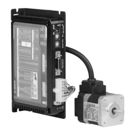
Autonics Ai-M-56LA Посібник - Сторінка 6
Переглянути онлайн або завантажити pdf Посібник для Контролер Autonics Ai-M-56LA. Autonics Ai-M-56LA 16 сторінок. Pulse train input type, servo system, dc type

两相步进电机马达样本闭环步进电机驱动器说明书 韩国Autonics步进伺服马达选型样本pdf资料
Output
1. In-Position
In-position output is motor drive complete signal and it is output when drive is complete by command pulses.
- When motor is arrived at the command position, in-position output is [H]. (position error=0)
- When drive is complete and motor rotates by the external force,
-1.8°≤ Position error ≤ 1.8° : In-position = [H]
Position error < -1.8°, Position error > 1.8° : In-position = [L]
The in-position LED turns ON/OFF depending on in-position output [H]/[L].
For accurate drive, check the in-position output again and execute the next drive.
※ Refer to example of output circuit connection.
2. ALARM OUTPUT
When alarm occurs, driver recognizes the alarm. The alarm LED (red) and alarm output represents the errors.
● Alarm output signal
-In case of normal status, output is [H]. When alarm occurs, output is [L].
-When supplying alarm reset, output turns [H].
※ Refer to example of output circuit connection.
● Alarm indicator
Depending on the number of flashing of alarm indicator, you can check alarm causes.
No. of flashing Alarm type
1
Over current error
2
Over speed error
3
Position tracking error
4
Over load error
5
Over heat error
6
Motor connection error
7
Encoder connection error When encoder cable connection error occurs at driver
※ Depending on alarm type, it flashes the number of flashing with 400ms
interval. The waited 800ms signals output repeatedly. Until clearing
alarm by alarm reset signal, alarm signal output continuously.
3. Example of output circuit connection
-It is recommended to use below 50VDC at VCC. Use the R
driver to be within 25mA following the below formula.
V
-0.7V-V
※A: R
=
- 10Ω
CC
F
L
0.025A
(V
is LED forward voltage of primary photocoupler.)
F
A. Circuit with photo coupler
Controller
VCC
+
-
B. Circuit with pull up (reversed)
VCC
R
L
+
10Ω
-
奥托尼克斯电子中国autonics电机热线 4006-022-002
Closed-Loop Stepper Motor System
Descriptions
When over current flows at motor RUN element
When motor speed is over 4,000rpm
When motor does not track the pulse input normally
When applying over the rated load for over 1 sec.
When driver inner temperature is over 80℃
When supplying power without connecting motor cable to the driver
V
-0.7V
※B,C: R
=
CC
L
0.025A
Driver
+
10Ω
R
L
-
Driver
1
2
400ms
for I
(collector current of secondary detector) of photo coupler inside the
L
C
- 10Ω
C. Circuit with pull down (not-reversed)
VCC
+
10Ω
-
R
L
深圳 北京 上海 株洲 天津 青岛
3
1
2
3
800ms
Driver
(A)
Photoelectric
Sensors
(B)
Fiber
Optic
Sensors
(C)
Door/Area
Sensors
(D)
Proximity
Sensors
(E)
Pressure
Sensors
(F)
Rotary
Encoders
(G)
Connectors/
Sockets
(H)
Temperature
Controllers
(I)
SSRs / Power
Controllers
(J)
Counters
(K)
Timers
(L)
Panel
Meters
(M)
Tacho /
Speed / Pulse
Meters
(N)
Display
Units
(O)
Sensor
Controllers
(P)
Switching
Mode Power
Supplies
(Q)
Stepper Motors
& Drivers
& Controllers
(R)
Graphic/
Logic
Panels
(S)
Field
Network
Devices
(T)
Software
Q-7
