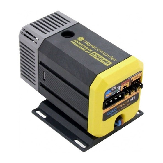
Aqua Computer AQUASTREAM XT USB Посібник користувача та інструкція з експлуатації - Сторінка 10
Переглянути онлайн або завантажити pdf Посібник користувача та інструкція з експлуатації для Водяний насос Aqua Computer AQUASTREAM XT USB. Aqua Computer AQUASTREAM XT USB 16 сторінок.
Також для Aqua Computer AQUASTREAM XT USB: Посібник з експлуатації та встановлення (20 сторінок)

aqua
computer
Version 11/2007
MANUAL AQUASTREAM XT
8.1. Installation der aquasuite Software
To be able to control and monitor the aquastream XT over a Windows(1) PC,
we offer the aquasuite software as a free download on our website
www.aqua-computer .de
. You find the latest version of the software in the
support area.
In addition you need the Microsoft
(1)
.NET framework
(1)
2.0 or higher. You
find this this also in our download area. If you use Windows Vista
(1)
, you do
not need this program, since it is already integrated into the operating system.
Please install the Microsoft
(1)
.NET framework
(1)
first and if necessary restart the
computer. If the program creates a new user account you can just delete it in
the control panel.
Then install the aquasuite software. After the installation the aquasuite
software is immediately ready for use. Depending on the chosen settings the
aquasuite starts at the next restart automatically or can be started via the icon
on the desktop or through the start menu.
The following sites describe the functions of each window in the aquasuite
software.
(1)
Microsoft, Windows, .NET framework and Windows Vista are registered
trademarks of Microsoft Corporation.
8.2. Window „aquastream"
You see all important data summarized compactly in the main view. The
graphic representation of the pump shows the water temperature on the left
and on the right side the water flow rate if a ultra variant of the pump is used
and an optionally available flow sensor was attached to the pump.
A ring-like indicator within the pump shows information about the adjusted
frequency with its blue segments. The more blue segments are visible, the
higher the frequency of the pump is. You find a similar indication in the
graphic representation of the ventilator. The segments show information
about the adjusted performance here.
The output voltage as well as the performance is displayed above the
ventilator.
The scale on the right side shows the temperature of the optionally available
external sensor. The little red triangle marks the adjusted alarm temperature.
General operating data of the pump can be found in the upper left field. The
current status of the pump as well as possible faults are displayed in the field
at the end of the window.
Page 10
Aqua Computer GmbH und Co. KG
© 2007
Gelliehäuser Str. 1 – D-37130 Gleichen - Germany
