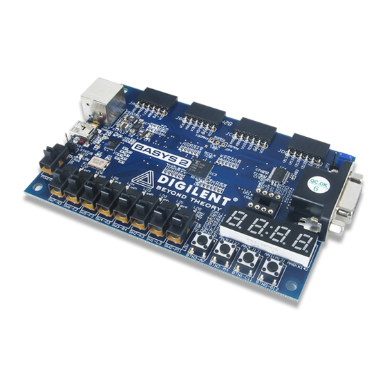
Digilent Basys 2 Довідковий посібник - Сторінка 5
Переглянути онлайн або завантажити pdf Довідковий посібник для Комп'ютерне обладнання Digilent Basys 2. Digilent Basys 2 12 сторінок. Fpga board

Basys2™ FPGA Board Reference Manual
Common anode
AN1
AN2
AN3
AN4
CA CB CC CD CE CF CG DP
Four-digit Seven
Segment Display
For each of the four digits to appear bright and continuously illuminated, all four digits should be driven once every
1 to 16ms (for a refresh frequency of 1KHz to
60Hz). For example, in a 60Hz refresh scheme,
the entire display would be refreshed once every
16ms, and each digit would be illuminated for ¼
of the refresh cycle, or 4ms. The controller must
assure that the correct cathode pattern is
present when the corresponding anode signal is
driven. To illustrate the process, if AN1 is
asserted while CB and CC are asserted, then a
"1" will be displayed in digit position 1. Then, if
AN2 is asserted while CA, CB and CC are
asserted, then a "7" will be displayed in digit
position 2. If A1 and CB, CC are driven for 4ms, and then A2 and CA, CB, CC are driven for 4ms in an endless
succession, the display will show "17" in the first two digits. Figure 8 shows an example timing diagram for a four-
digit seven-segment controller.
5
PS/2 Port
The 6-pin mini-DIN connector can accommodate a PS/2 mouse or keyboard. The PS/2 connector is supplied with
5VDC.
Both the mouse and keyboard use a two-wire serial bus (clock and data) to communicate with a host device. Both
use 11-bit words that include a start, stop and odd parity bit, but the data packets are organized differently, and
the keyboard interface allows bi-directional data transfers (so the host device can illuminate state LEDs on the
keyboard). Bus timings are shown in the figure.
The clock and data signals are only driven when data transfers occur, and otherwise they are held in the "idle"
state at logic '1'. The timings define signal requirements for mouse-to-host communications and bi-directional
keyboard communications. A PS/2 interface circuit can be implemented in the FPGA to create a keyboard or
mouse interface.
Copyright Digilent, Inc. All rights reserved.
Other product and company names mentioned may be trademarks of their respective owners.
A
B
F
G
C
E
DP
D
Individual cathodes
Figure 7. Seven-segment display.
AN0
AN1
AN2
AN3
Cathodes
An un-illuminated seven-segment display, and nine
illumination patterns corresponding to decimal digits
Refresh period = 1ms to 16ms
Digit period = Refresh / 4
Digit 0
Digit 1
Digit 2
Figure 8. Multiplexed 7seg display timing.
Digit 3
Page 5 of 12
