Siemens TRI-S Інструкція з монтажу - Сторінка 2
Переглянути онлайн або завантажити pdf Інструкція з монтажу для Блок управління Siemens TRI-S. Siemens TRI-S 4 сторінки. Fire safety, addressable interface modules
3. (Refer to Figure 3.) Follow the instructions in the
FPI-32 Programmer/Tester Manual (P/N 315-
090077) to program the TRI to the following:
a. Desired address
b. Desired application for fire or proprietary
burglary (security)
c. Normally open or normally closed switch
NOTES:
1. There can be any number of normally open switches.
2. The end of line resistor must be located at the last switch.
3. Do not wire a normally closed switch across the end of line
resistor.
Application
Fire Alarm
Normally Open
Fire Trouble
Normally Open
Fire Supervisory
Normally Open
Figure 3
Wiring Normally Open Switches
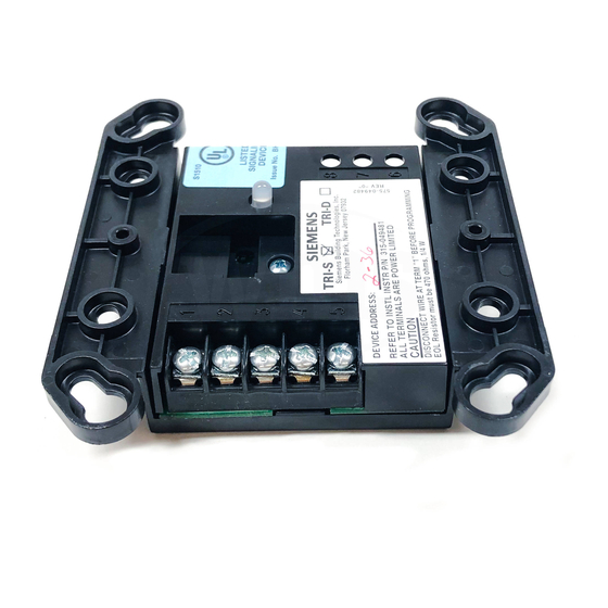
4. Record the device address on the label located on
the TRI front panel. The TRI can now be installed
and wired to the system.
WIRING
(Refer to Figures 4-8)
Refer to the appropriate wiring diagram below and wire
the addressable interface module accordingly.
Note: Recommended wire size:
18 AWG minimum
14 AWG maximum
Wire larger than 14 AWG can damage the
connector.
POWER LIMITED WIRING FOR TRI-R
ADDRESSABLE INTERFACE MODULE
In compliance with NEC Article 760, all power limited
fire protective signaling conductors must be separated
FPI-32
Switch
Device Use
Alarm
Trouble
Trouble
a minimum of
1
/
inch from all of the following items
4
located within an outlet box:
• electric light
• power
• Class 1 or non-power limited fire protective signal-
ing conductors
To meet the above the requirements, the following
guidelines must be observed when installing this
interface module.
NOTE: If power limited wiring is not used within this
outlet box, then the following guidelines do not
apply. In that case, be sure to follow standard
wiring practices.
TRI-R CONTROL MODULE BARRIER
The TRI-R Control Module Barrier must be used when
the TRI-R relay contacts are connected to non-power
limited lines. Install the barrier diagonally into the back-
box to create two separate compartments within the
backbox to separate the wires, as shown in Figure 4.
TABS
FACE
OUT
Installing the TRI-R Control Module Barrier
WIRING ENTERING OUTLET BOX
Power Limited Wiring
All power limited wiring must enter the outlet box
separately from the electric light, power, Class 1, or
non-powered limited fire protection signaling conduc-
tors. For the TRI-R, wiring to terminal block positions 1,
2, 3, 4, and 5 must enter the outlet box separately from
terminals 6, 7, and 8.
IMPORTANT:
Minimize the length of wire
entering the outlet box.
2
Backbox
TRI-R Control Module Barrier
Use P/N 330-096393 for
Double Gang Box
Use P/N 330-096384 for
4-inch Square Electrical Box
Figure 4