Siemens TRI-S Інструкція з монтажу - Сторінка 3
Переглянути онлайн або завантажити pdf Інструкція з монтажу для Блок управління Siemens TRI-S. Siemens TRI-S 4 сторінки. Fire safety, addressable interface modules
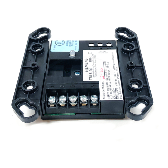
WIRING AT THE TERMINAL BLOCKS
Power Limited Wiring (Refer to Figure 5)
Wiring to positions 1, 2, 3, 4, and 5 is power limited.
Non-Power Limited Wiring
Wiring to positions 6, 7, and 8 is considered non-
power limited.
Note: Remove all slack from these wires by pulling
excess wiring back through the holes.
Figure 5
TRI-R Power Limited Wiring
NOTES:
1.
All supervised switches must be held closed and/or
open for at least a quarter of a second to guarantee
detection.
2.
Use ULI listed EOL Model EL-30/31 mounting plate
with 470 ohms,
1
/
W resistor, P/N 140-82016485. Order
4
Model EL-30/31 separately.
3.
The supervised switches have the following ratings:
Voltage maximum:
Current maximum:
Contact resistance maximum:
Maximum cable length:
C
:
Line to line
C
:
Line to shield
Max line size:
Min line size:
4.
Supervised switch S1 is on the first programmed
address, and Supervised switch S2 is on the second
programmed address.
5.
Relay contacts are rated: 4A, 125 VAC resistive
27 VDC
3.5mA during polling
10 ohms
200 feet (18 AWG)
0.02uF
0.04uF
14 AWG
18 AWG
3
Figure 6
Model TRI-R Wiring
Figure 7
Model TRI-S Wiring
Figure 8
Model TRI-D Wiring
4A, 30 VDC resistive
Inductive: 3.5A, 120 VAC (0.6P.F.)
3.0A, 30 VDC (0.6 P.F.)
2.0A, 120 VAC (0.4 P.F.)
2.0A, 120 VAC (0.35 P.F.)
2.0A, 30 VDC (0.35 P.F.)
The relay is shown in supervisory condition.