Cisco 2500 Series Посібник з розгортання - Сторінка 4
Переглянути онлайн або завантажити pdf Посібник з розгортання для Мережевий маршрутизатор Cisco 2500 Series. Cisco 2500 Series 23 сторінки. Wireless controller
Також для Cisco 2500 Series: Посібник з встановлення (12 сторінок), Посібник з конфігурації (19 сторінок), Посібник з конфігурації (50 сторінок), Посібник для початківців (47 сторінок)

♦
9600 baud
♦
8 data bits
♦
No flow control
♦
1 stop bit
♦
No parity
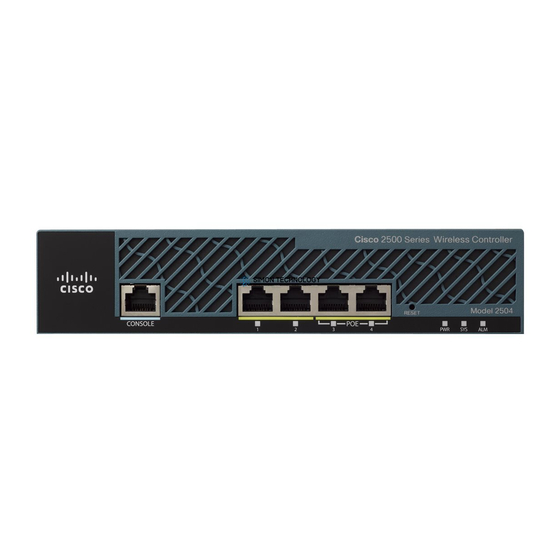
Cisco 2500 Series Wireless Controller has 4 Gigabit Ethernet ports. Each port is, by default, an 802.1Q
VLAN trunk port. The VLAN trunking characteristics of the port are not configurable.
An interface is a logical entity on the controller. An interface has multiple parameters associated with it,
including IP address, default−gateway (for the IP subnet), primary physical port, secondary physical port,
VLAN tag, and DHCP server. Since LAG is not used, each interface is mapped to at least one primary
physical port and an optional secondary port. Multiple interfaces can be mapped to a single Wireless
Controller port.
There are multiple types of interfaces on the Wireless Controller, four of which are static types that must be
present and are configured at setup time:
•
Management interface (static and configured at setup time; mandatory)
•
AP−manager interface Not required for the Cisco 2500 Series Wireless Controller
•
Virtual interface (static and configured at setup time; mandatory)
•
Dynamic interface (user−defined)
The management interface is the default interface for in−band management of the controller and
connectivity to enterprise services such as AAA servers. The management interface is also used for
communications between the controller and APs. The management Interface is the only consistently
"pingable" in−band interface IP address on the controller. The management interface will act like an AP
manager interface by default.
The dynamic interface with the Dynamic AP Management option enabled on it is used as the tunnel source
for packets from the controller to the AP, and as the destination for CAPWAP packets from the AP to the
controller. The dynamic interfaces for AP manager must have a unique IP address. Typically, this is
configured on the same subnet as the management interface, but this is not necessarily a requirement. In the
case of the Cisco 2500 Series Wireless Controller, a single dynamic AP manager can support any number of
APs. However, as a best practice, it is suggested to have 4 separate dynamic AP manager interfaces and
associate them to the 4 Gigabit interfaces. By default, the management interface acts like an AP−manager
interface as well and it is associated to one Gigabit interface. As a result, if you are using the management
interface, you need to create only 3 more dynamic AP manager interfaces and associate them to the remaining
3 Gigabit interfaces.
The virtual interface is used to support mobility management, DHCP relay, and embedded layer 3 security
like guest web authentication and VPN termination. The virtual interface must be configured with an
unassigned and unused gateway IP address. A typical virtual interface is 1.1.1.1. The virtual interface address
is not pingable and should not exist in any routing table in your network.
Dynamic interfaces are created by users and are designed to be analogous to VLANs for wireless LAN client
device. The Cisco 2500 Series Wireless Controller will support up to 16 dynamic interfaces. Dynamic
interfaces must be configured on a unique IP network and VLAN. Each dynamic interface acts as a DHCP
relay for wireless clients associated to wireless LANs (WLANs) mapped to the interface. A WLAN associates
an SSID to an interface and is configured with security, QoS, radio policies, and other wireless network
parameters. There can be up to 16 WLANs configured per controller.
Note: Link Aggregation (LAG) is not supported on the Cisco 2500 Series Wireless Controller.
