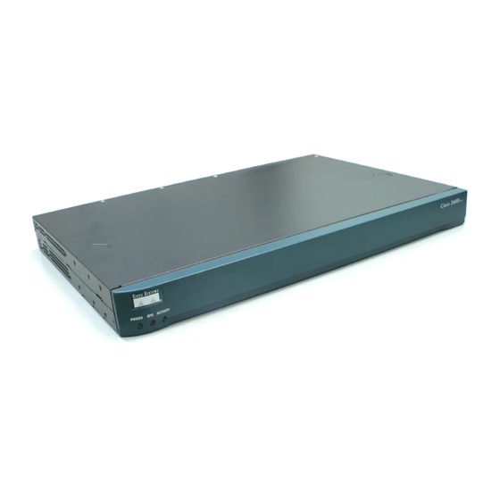
Cisco 2691 Series Посібник із швидкого старту - Сторінка 14
Переглянути онлайн або завантажити pdf Посібник із швидкого старту для Мережеве обладнання Cisco 2691 Series. Cisco 2691 Series 29 сторінок. Modular routers
Також для Cisco 2691 Series: Встановлення та форматування (34 сторінок), Технічний паспорт (8 сторінок), Посібник користувача (48 сторінок)

If you connect dual DC power sources, both sources must be the same polarity. Do not connect a –DC with a +DC
Caution
source to a Cisco 2691 router. Opposite-polarity sources damage the power supply.
DC Wiring Requirements
A Cisco 2691 router with a DC-input power supply requires copper wire for the power connections. Table 2 summarizes the
wiring requirements.
You can connect a single DC power source to either the A input or the B input. If there are dual power sources, connect one
source to the A input and one source to the B input; both sources must be the same polarity and voltage.
For installations compliant with the National Electric Code, AWG 14 (2.0 mm
Note
safety ground wire.
Table 2
DC Wiring Requirements for Cisco 2691 Routers
Installed Power Supply
2
Nominal 24/48 VDC
1. See the note above this table for National Electric Code wire size requirements.
2. The input voltage tolerance limits for nominal 24/48 V power supplies are 18 and 72 VDC.
Wiring Procedure for DC Input
To connect the router to a DC power source, perform the following steps:
Step 1
Remove power from the DC circuit. To ensure that power is removed from the DC circuit, locate the circuit breaker for
the DC circuit, switch the circuit breaker to the OFF position, and tape the circuit-breaker switch in the OFF position.
Warning
Before performing any of the following procedures, ensure that power is removed from the DC circuit.
Statement 1003
Secure all power cabling when installing this unit to avoid disturbing field-wiring connections.
Tip
Strip the wires to the appropriate length for the terminals. The strip length is 3/16 in. to 1/4 in. (5 mm to 7 mm).
Step 2
Remove the plastic covers from the terminal block. Save them for reinstallation after you finish wiring.
Step 3
Do not remove the colored screw at either end of the terminal block. Those are the terminal mounting screws.
Note
Step 4
Connect the wires to the terminal block, starting with the safety ground wire. Insert each wire into the appropriate
terminal as shown in Figure 8. To avoid interference with the on/off switch, insert the wires from below. Tighten the
terminal screws to 8.0 ± 0.5 in-lb (0.9 ± 0.05 N-m).
14
DC Input
24 - 36 V, 8 A, positive or negative,
single or dual sources
36 - 60 V, 4 A, positive or negative,
single or dual sources
2
) wire is required for DC input and
DC Input
Safety Ground
1
Wire Size
Wire Size
AWG 18
AWG 14
2
2
(1.0 mm
)
(2.0 mm
AWG 18
AWG 14
2
2
(1.0 mm
)
(2.0 mm
Overcurrent
Protection
15 A maximum
)
15 A maximum
))
