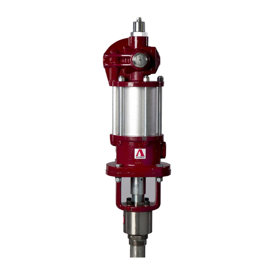
Alemite 7896-A5 Посібник з експлуатації - Сторінка 10
Переглянути онлайн або завантажити pdf Посібник з експлуатації для Водяний насос Alemite 7896-A5. Alemite 7896-A5 16 сторінок. Medium-pressure material pump

SER 7896-A5
Pump Tube
15. Unscrew Valve Body (47) from Cylinder (43).
16. Remove O-Ring (42) from the Cylinder.
17. Remove Stop Washer (44), Washer (45), and Ball (46)
from the Valve Body.
18. Push Rod (11) out the Extension Cylinder.
• Remove the Rod assembly from the Cylinder.
19. Remove upper and lower Spring Clips (10) that secure
Extension Rod (33) and Stem (34) to lower
Coupling (9).
20. Unscrew the Rod assembly and the Stem assembly
from the Coupling.
21. Clamp the flats of the Stem assembly in a vise.
22. Unscrew Valve (41) from the Stem.
23. Remove the Body and V-Packing assembly from the
Stem.
24. Remove Stop (35) from the Stem.
25. Unscrew Valve Seat (40) from Guide (36).
26. From the top of the Body remove:
• Spring (37) ...................................................... Qty 1
• Washer (22) ..................................................... Qty 1
• Male Ring (38) ................................................ Qty 1
• V-Packings (24)............................................... Qty 5
• Female Ring (39) ............................................. Qty 1
27. Unscrew Coupling (32) from Cylinder (43).
• Use two strap wrenches.
28. Remove additional O-Ring (42).
29. Unscrew Extension Cylinder (31) from the Coupling.
30. Remove additional O-Ring (30).
Optional Procedures
31. Unscrew Rod (11) from Extension Rod (33) as
required.
32. Remove Screws (13) and Lock Washers (14) that
secure Plate (15) to the Body as required.
• Remove the Plate from Upper Mounting (16).
33. Remove Hydraulic Fitting (17) as required.
34. Unscrew Valve Seat (20) with Screw (21) as required.
Revision (2-04)
Medium-Pressure Material Pump
Clean and Inspect
NOTE: Use the appropriate repair kit for
replacement parts. Make sure all the compo-
nents are included in the kit before discard-
ing used parts.
1. Clean all metal parts in a modified petroleum-based
solvent. The solvent should be environmentally safe.
2. Make sure to remove the thread sealant from both
male and female threaded connections.
3. Inspect all parts for wear and/or damage.
• Replace as necessary.
4. Inspect Rod (11) and Cylinder (43) closely. Use a
magnifying glass to detect any score marks.
• Replace as necessary.
5. Closely inspect the mating surfaces of all check valve
components for any imperfections. Ensure a smooth
and clean contact is obtained when assembled.
EXAMPLE: Place Ball (46) into Valve
Body (47). Fill the Valve Body with solvent.
Make sure no leakage occurs.
Assembly
NOTE: Prior to assembly, certain compo-
nents require lubrication in clean oil. Refer
to Table 4 for details.
Body Packing
NOTE: Refer to Figure 7 for a section view
of the Pump Tube Assembly.
1. Position Body (19) large diameter upward.
2. Install and seat the following components in order:
• Washer (22) ......................................................Qty 1
• Female Ring (23) [concave surface upward]....Qty 1
• V-Packings (24) [concave surface upward]..... Qty 4
• Male Ring (25) [flat surface upward]...............Qty 1
• Washer (22) ......................................................Qty 1
• Lantern Ring (26)............................................ Qty 1
• Washer (22) ......................................................Qty 1
• Female Ring (23) [concave surface upward]....Qty 1
• V-Packings (24) [concave surface upward]..... Qty 4
• Male Ring (25) [flat surface upward]...............Qty 1
Item No.
on Figure 3-B
24
V-Packing (Buna-N and Teflon)
30
O-Ring, 1-3/4 " ID x 1-7/8 " OD
32
O-Ring, 1-7/8 " ID x 2 " OD
Table 4 Lubricated Components
10
Description
Alemite Corporation
