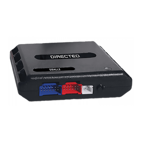
Directed Electronics Xpresskit DBALL Посібник з монтажу - Сторінка 9
Переглянути онлайн або завантажити pdf Посібник з монтажу для Автомобільні аксесуари Directed Electronics Xpresskit DBALL. Directed Electronics Xpresskit DBALL 14 сторінок. Databus all combo bypass module
Також для Directed Electronics Xpresskit DBALL: Посібник з монтажу (14 сторінок)

Platform: DBALL/DBALL2
Firmware: GM5 Remote Start Ready (RSR) Installation
LED Diagnostics and Troubleshooting
LED
Status
Module Programming
Solid red
Solid
Flashes x1
Flashes red x1
Flashes red x3
Flashes x3
Solid red 3 sec.
Solid Red
3 sec.
Flashes orange
Flashes
Flashes orange x1
Flashes x1
Flashes orange x2
Flashes x2
Flashes orange x3
Flashes x3
Flashes orange &
Flashes
green
Flashes green x1
Flashes x1
Flashes green x2
Flashes x2
Flashes green x3
Flashes x3
Flashes
Flashes green
Description
Waiting for bus detection.
Data bus detection timeout.
Bypass detection timeout.
The Saturn Ion type of bypass
programmed, but J1850 did not.
Waiting for the bypass to
program.
Programming completed.
Programming completed.
Programming completed.
Waiting for keyless
programming.
Programming completed.
Programming completed.
Programming completed.
Analogue bypass programming
in progress, waiting on more
information to complete the
sequence.
Troubleshooting
If the key was turned to IGNITION:
To know if the bus is detected, connect the pink ignition
input wire from the black 10-pin connector to (+) 12v.
If the LED starts flashing orange:
The bus was detected, but the ignition was not detected in
data. In this case, connecting the pink ignition input wire
from the black 10-pin connector will fix the issue.
J1850 was not detected. Refer to the wiring diagram to
verify your connections to the vehicle.
Bypass was not detected after a timeout period. Refer to
the wiring diagram to verify your connections to the vehicle.
J1850 was not detected. Refer to the wiring diagram to
verify your connections to the vehicle.
Waiting for the key to be at the START position. If it was
already turned to that position, start is not being seen in
data. Connect the violet start input wire from the black 10-
pin connector on the module.
Bypass detected = PassLock 1 door lock is on ISO.
Bypass detected = PassLock 2 door lock is on ISO.
Bypass detected = PassLock 3 door lock is on ISO.
The module detected the ISO door lock. Press lock or
unlock on the OEM FOB to validate your installation. If it
does not work, refer to the wiring diagram to verify your
connections. If the OEM FOB is not available, it is possible
to skip the keyless programming by pressing 5 times on
the programming button. The LED will go to the final
status, and it will then turn OFF. The module will be
programmed in ISO door lock anyway.
Bypass detected = PassLock 1 door lock is on J1850.
Bypass detected = PassLock 2 door lock is on J1850.
Bypass detected = PassLock 3 door lock is on J1850.
If the key was turned back to IGNITION, the module did not
move to the next step because it noticed an error in the
second recorded value. Refer to the wiring diagram to verify
your MUX connections. It is possible to skip the bypass by
pressing 5 times on the programming button. The LED will
turn ON solid red for 3 seconds, and then it will turn OFF
to indicate the bypass was skipped. The module will only
do convenience in this case.
Rev.: 20150626
Page 9
© 2015 Directed. All rights reserved.
