Distech Controls IO-R-34 Посібник - Сторінка 7
Переглянути онлайн або завантажити pdf Посібник для Блок управління Distech Controls IO-R-34. Distech Controls IO-R-34 19 сторінок. Remote module
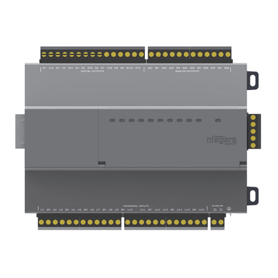
IO-R-34 Board Layout and Terminal Locations
IO-R-34 Board Layout and Terminal Locations
The IO-R-34 provides 16 universal
100K ohm resistive, or Type 3 thermistor temperature sensors, and 18 outputs: 10 relay (24Vac/dc, 0.5A max.)
outputs and 8 analog outputs (0–10 Vdc). Wiring terminal positions are shown in
Figure 3
IO-R-34 Wiring Terminal Locations.
D1 1C2 D2 D3 3C D4 D5 5C6 D6 DY 7C8 D8 D9
Relay Output
LEDs (Yellow)
P-
P+
RS-485-
RS485+
RS-485 S
5 pin connector
15Vdc Output
Power
RS-485
U1 0V U2 U3 0V U4 U5 0V U6 U7 0V U8
Wiring Details
See
Figure 3
above to locate connectors and other components on the IO-R-34 module.
Make connections to the IO-R-34 in the following order.
Connect the earth grounding wire (with spade connector) from the earth ground lug on the IO-R-34 to a nearby
1.
earth grounding point. See
Wire the supply power to the IO-R-34, but do not energize the power source until all other wiring is completed.
2.
See
"Power Wiring"
Connect RS-485 wiring between the IO-R-34 and the EC-BOS-8, and (if applicable) to other modules (for
3.
example: IO-R-16, IO-R-34, or IO-16-485) in a continuous multidrop fashion. See sections
Communications"
on page 9,
Connect S terminal wiring as shown in
Caution
as reference ground between isolated RS-485 ports on EC-BOS-8 and IO-R-16 and IO-R-34 modules.
Apply power to the unit. See
4.
Remote IO-R-34 Module Mounting and Wiring Guide
inputs
compatible with 0–10Vdc, 0–20mA, dry contacts, pulsing dry contacts, 0–
Digital Relay Outputs (D1-10)
U9 0V U10 U11 0V U12 U13 0V U14 U15 0V U16
Universal Inputs (U1-16)
"Grounding"
for details.
for details.
"Inputs"
on page 10, and
"Power up and Initial Checkout,"
IO-R-34 Board Layout and Terminal Locations
Analog Vdc Outputs (A01-8)
9C10
D10
A01 0V A02 A03 0V A04 A05 0V A06 A07 0V A08
DL 11
"Outputs"
on page 13.
Figure 6
or communication errors may result. S terminal serves
page 15.
August 2, 2017
Figure
3, along with LED locations.
Status LED
(Green)
P-
P+
RS-485-
RS485+
RS-485 S
5 pin connector
15Vdc Power
RS-485
Earth Ground
Connector Lug
24Vac or Vdc
Power
"RS-485
7