Balmar 97EHD Series Посібник з монтажу та експлуатації - Сторінка 12
Переглянути онлайн або завантажити pdf Посібник з монтажу та експлуатації для Портативний генератор Balmar 97EHD Series. Balmar 97EHD Series 20 сторінок. Alternator
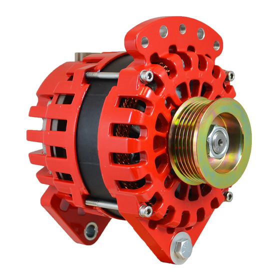
Single-foot and Vortec mount versions Isolated Ground:
1.
Positive Output Terminal - Must be connected via properly-sized
cable to the battery or batteries being charged. Cable size is determined by
alternator output and length of cable run. See Page 3 for wiring size chart.
2. Stator Output Wire (WHITE) - Provides an unrectified source of AC voltage
which can be used as a signal for an electric tachometer.
3. External Field Wire (BLUE) - Connects to external voltage regulator via
wiring harness.
4. Internal Regulator Excite Wire (BROWN) - Provides switched source
of voltage to the alternator's internal regulator. Only connected when the
internal regulator is being used.
5. Internal Regulator Voltage Sense Wire (RED) - Provides sensing voltage
when the internal regulator is used.
6. Negative Terminal (Ground) - Must be connected to system ground via
properly sized cable. Cable size is determined by alternator output and
length of cable run. See Page 3 for wiring size chart. Ensure that the ground
cable is adequately supported to supply strain relief. The wire exiting the
alternator and attached to this terminal MUST remain in place for the alter-
nator to function.
7. Temp Sensor - Install the ring terminal end of the (Optional) MC-TS-A here.
Do not bend the heat shrink or ring terminal.
CAUTION: Positive Output and Negative (Ground) cable must be properly
supported to ensure that terminal posts are protected from excessive
weight and torque. Failure to provide adequate strain relief could result in
damage to the alternator and cables.
2
1
NOTES
Page
12
3
XT-SF-170-IG-XX shown. Wiring is
the same for Vortec model XT-VT-170-
IG-XX
4
5
7
6