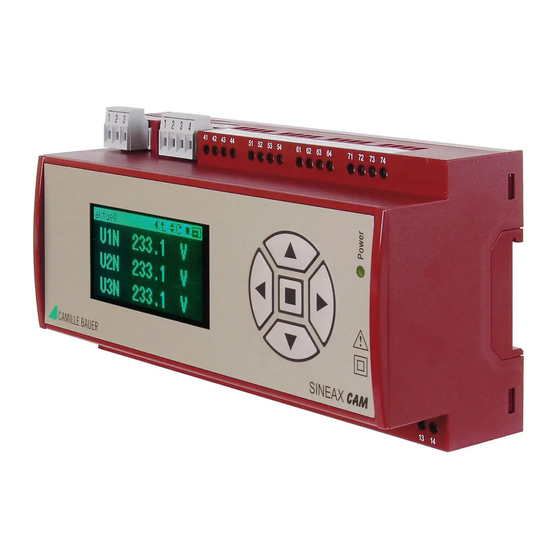
Camille Bauer SINEAX CAM Інструкція з експлуатації Посібник з експлуатації - Сторінка 3
Переглянути онлайн або завантажити pdf Інструкція з експлуатації Посібник з експлуатації для Вимірювальні прилади Camille Bauer SINEAX CAM. Camille Bauer SINEAX CAM 12 сторінок. Graphic display for sineax cam
Також для Camille Bauer SINEAX CAM: Інструкція з експлуатації Посібник з експлуатації (19 сторінок)

Snap housing on the top-hat rail (EN 50 022) (see Fig. 1).
Fig. 1. Mounting on top-hat rail 35 x 15 or 35 x 7.5 mm.
4.2 Releasing
Remove the housing from the mounting rail according to
Figure 2.
Fig. 2
5. Electrical connections
Screw connections are used. They are designed for cross
sections of 4 mm
2
for single wire leads and 2 x 2.5 mm
multiwire leads.
Ensure under all circumstances that the leads are
free of potential when connecting them!
Please observe, ...
... that the data on the type plate must be adhe-
red to!
A marked and easily accessible switch for turning off the
power supply has to be arranged in the vicinity of the
device.
In case of a supply of direct current > 125 V DC, an
external fuse has to be provided in the power supply
circuit.
Otherwise, the national provisions (e.g. in Germany VDE
0100 "Conditions concerning the erection of heavy cur-
rent facilities with rated voltages below 1000 V") have to
be observed in the installation and material selection of
electric lines!
5.1 Inputs and outputs
Analog outputs
R ext
R ext
x = 4..7
x1
x2 x3 x4
C1+
C1- C2+ C2-
i = 1..4
I/O i:
0-20 mA
2
for
Analog inputs
+
-
+
-
I
I
x = 4..7
x1
x2 x3 x4
C1+
C1- C2+ C2-
i = 1..4
I/O i:
0-20 mA
Digital outputs 12/24 V DC
x = 4..7
x1
x2 x3 x4
+
C1
C2 C3
i = 1..4
I/O i:
Digital I/O
1) Recommended if input resistance > 100 kΩ
Digital inputs 12/24 V DC
24 VDC
+
x = 4..7
x1
x2 x3 x4
C2 C3 +out
C1
-inp
I/O i:
Digital I/O
i = 1..4
Digital inputs 125 V DC
125 VDC
+
71
72 73 74
C2 C3 +out
C1
-inp
I/O 4:
Digital I/O
Modbus
Subbus
+A –B
V+
+A –B
GND
GND
USB
I/O 1
1
2
3
1
2
3 4
41
42 43 44
USB
21 22
23
31
32
33
1
3
4
6
k
l
k
l
Rel 1
Rel 2
I 1
I 2
Rel 1
Rel 2
21
22
23
31
32
33
+
Rel.
24 V
–
IN
22 kΩ
Counter
1)
COM
HV-Input 110/230 VAC
110-230 VAC
~
71
72 73 74
~
I/O 4:
110/230 V
I/O 2
I/O 3
I/O 4
51 52 53 54
61 62 63 64
71 72 73 74
7
9
10
12
2
5
8
11
k
l
k
l
U 1
U 2
U 3
N
Power supply
I 3
I N
When the device is switched
off, the status of the relay
contact is not defined.
Dangerous voltages may
occur.
~
13 14
3
