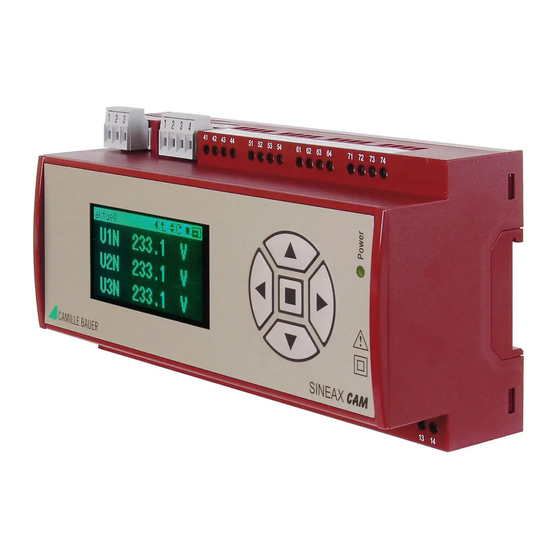
Camille Bauer SINEAX CAM Kullanım Talimatları Kılavuzu - Sayfa 3
Ölçüm Cihazları Camille Bauer SINEAX CAM için çevrimiçi göz atın veya pdf Kullanım Talimatları Kılavuzu indirin. Camille Bauer SINEAX CAM 12 sayfaları. Graphic display for sineax cam
Ayrıca Camille Bauer SINEAX CAM için: Kullanım Talimatları Kılavuzu (19 sayfalar)

Snap housing on the top-hat rail (EN 50 022) (see Fig. 1).
Fig. 1. Mounting on top-hat rail 35 x 15 or 35 x 7.5 mm.
4.2 Releasing
Remove the housing from the mounting rail according to
Figure 2.
Fig. 2
5. Electrical connections
Screw connections are used. They are designed for cross
sections of 4 mm
2
for single wire leads and 2 x 2.5 mm
multiwire leads.
Ensure under all circumstances that the leads are
free of potential when connecting them!
Please observe, ...
... that the data on the type plate must be adhe-
red to!
A marked and easily accessible switch for turning off the
power supply has to be arranged in the vicinity of the
device.
In case of a supply of direct current > 125 V DC, an
external fuse has to be provided in the power supply
circuit.
Otherwise, the national provisions (e.g. in Germany VDE
0100 "Conditions concerning the erection of heavy cur-
rent facilities with rated voltages below 1000 V") have to
be observed in the installation and material selection of
electric lines!
5.1 Inputs and outputs
Analog outputs
R ext
R ext
x = 4..7
x1
x2 x3 x4
C1+
C1- C2+ C2-
i = 1..4
I/O i:
0-20 mA
2
for
Analog inputs
+
-
+
-
I
I
x = 4..7
x1
x2 x3 x4
C1+
C1- C2+ C2-
i = 1..4
I/O i:
0-20 mA
Digital outputs 12/24 V DC
x = 4..7
x1
x2 x3 x4
+
C1
C2 C3
i = 1..4
I/O i:
Digital I/O
1) Recommended if input resistance > 100 kΩ
Digital inputs 12/24 V DC
24 VDC
+
x = 4..7
x1
x2 x3 x4
C2 C3 +out
C1
-inp
I/O i:
Digital I/O
i = 1..4
Digital inputs 125 V DC
125 VDC
+
71
72 73 74
C2 C3 +out
C1
-inp
I/O 4:
Digital I/O
Modbus
Subbus
+A –B
V+
+A –B
GND
GND
USB
I/O 1
1
2
3
1
2
3 4
41
42 43 44
USB
21 22
23
31
32
33
1
3
4
6
k
l
k
l
Rel 1
Rel 2
I 1
I 2
Rel 1
Rel 2
21
22
23
31
32
33
+
Rel.
24 V
–
IN
22 kΩ
Counter
1)
COM
HV-Input 110/230 VAC
110-230 VAC
~
71
72 73 74
~
I/O 4:
110/230 V
I/O 2
I/O 3
I/O 4
51 52 53 54
61 62 63 64
71 72 73 74
7
9
10
12
2
5
8
11
k
l
k
l
U 1
U 2
U 3
N
Power supply
I 3
I N
When the device is switched
off, the status of the relay
contact is not defined.
Dangerous voltages may
occur.
~
13 14
3
