Altronix AL1002ADA220 Посібник з монтажу - Сторінка 3
Переглянути онлайн або завантажити pdf Посібник з монтажу для Подовжувач Altronix AL1002ADA220. Altronix AL1002ADA220 17 сторінок. Nac power extender
Також для Altronix AL1002ADA220: Посібник із застосування (8 сторінок)
AC Input:
Output:
Battery
Stand-by/Alarm
Current Consumption:
EOL Resistor (end of line): 2.2K (2200 Ohm), Altronix Model # AL-EOL22 (included).
Ground fault maximum
test impedance:
Stand-by Batteries
24VDC/7AH
24VDC/12AH (use two (2) 12VDC batteries in series)
24VDC/36AH
Note: Unit is equipped with 1A max. auxiliary output: "AUX" will remain battery backed up during power
outage. For loads connected to "AUX" please refer to battery "Stand-by Specifications" above for rat-
ings. When loads are connected to "AUX" output during alarm condition, the remaining outputs may, not
exceed 10A total alarm current (example: AUX = 1A, outputs up to 9A).
Wiring methods shall be in accordance with the National Electrical Code/NFPA 70/NFPA 72/ANSI, and with all
local codes and authorities having jurisdiction.
Product is intended for indoor dry use only.
Carefully review:
Application Guide for AL602ADA220, AL802ADA220, AL1002ADA220
Power Supply Specifications
Stand-by Specifications
Output Programming Selection Table
Sync Mode Selection Table
Terminal Identification Table
LED Status Indication Table
1. Mount the unit in the desired location. Mark and predrill holes in the wall to line up with the top two keyholes
in the enclosure. Install two upper fasteners and screws in the wall with the screw heads protruding. Place
the enclosure's upper keyholes over the two upper screws; level and secure. Mark the position of the lower
two holes. Remove the enclosure. Drill the lower holes and install two fasteners. Place the enclosure's upper
keyholes over the two upper screws. Install the two lower screws and make sure to tighten all screws
(Enclosure Dimensions, pg. 16). Secure enclosure to earth ground. Small terminal block wire gauges range
from 16 AWG to 24 AWG, all others range from 14 AWG to 24 AWG.
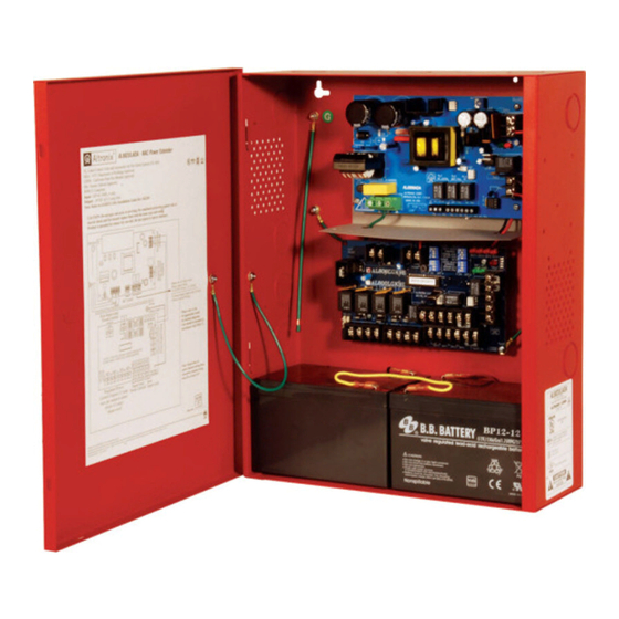
2. Secure ground wire lead to earth ground lug (Fig 1). Connect the line (L) and neutral (N) terminals to a
separate unswitched AC circuit (220VAC, 50/60Hz) dedicated to the Fire Alarm System.
3. Measure output voltage before connecting devices.This helps avoiding potential damage.
4. Connect battery to the terminals marked [– BAT +] on the Power Supply Board (battery leads included).
Use two (2) 12VDC batteries connected in series.
Note: If batteries being used in your installation do not fit into the AL1002ADA220 unit, it is required to
install a separate enclosure, UL Listed for appropriate application. Separate battery enclosure is required to
have 50 cubic inches of additional open space. All wiring methods shall be in accordance with the National
Electrical Code NFPA 70/NFPA 72/ANSI and with all local codes and authorities having jurisdiction.
AL1002ADA220 Installation Guide
Power Supply Specifications:
Nominal 220VAC (working range 198VAC - 256VAC), 50/60Hz, 2.5A.
Four (4) regulated supervised NAC output circuits, 24VDC, 2.5A maximum current.
One (1) aux. special application 24VDC power output circuit 1A, non-supervised
total output current must not exceed current 10A in Alarm Condition.
Use two (2) 12VDC / 7AH, two (2) 12VDC / 12AH or two (2) 12VDC / 40AH
batteries connected in series.
130mA/300mA
1000 Ohm.
Stand-by Specifications:
Installation Instructions:
(pg. 3)
(pg. 3)
(pg. 4)
(pg. 5)
(pgs. 6-7)
(pg. 7)
Stand-by Time Total
(A/Minutes)
24 Hours
24 Hours
24 Hours
Alarm Output
Aux. Output
Current
10A/5 minutes
10A/5 minutes
50mA
10A/5 minutes
Ground Lug
Line
–
1A
Fig. 1
L
N
Neutral
- 3 -