Advanced Axis AX Series Handbuch für Installation und Betrieb - Seite 13
Blättern Sie online oder laden Sie pdf Handbuch für Installation und Betrieb für Kontrolleinheit Advanced Axis AX Series herunter. Advanced Axis AX Series 18 Seiten. Conventional zone module

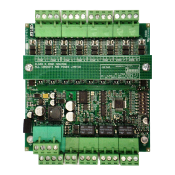
2.4.6 Multiple AX-CZM Module Power and Reset Wiring
24
VDC
Host Panel Reset Input
(momentary short/contact closure)
Host Panel Reset Input
(momentary short/contact closure)
Figure 13 – Multiple AX-CZM Module Power and Reset Wiring
Note: Loss of 24 VDC will transfer the failsafe (inverted) trouble relay contact. The HOST FACP normally
open (momentary closed for reset) input is unsupervised, wiring must be within 20 feet of the reset contact
in conduit.
www.advancedco.com
www.advancedco.com
+
-
+
-
+
-
+
-
+
ZONE 1
ZONE 2
ZONE 3
ZONE 4
ZONE 5
CLASS B ZONE MONITOR
ALL CIRCUITS ARE POWER LIMITED
REL1 / FIRE
0V
24V
A PBUS B
I/P
MON
COM
N/C
(--)
(+)
-
+
-
+
-
+
-
ZONE 6
ZONE 7
ZONE 8
ADDRESS
SETUP
ON
1
ON = PBUS MODULE
ON = CLASS A / OFF = CLASS B
ON = EARTH MONITOR ACTIVE
TX
RX
HB
REL2 / TROUBLE
REL3 / EARTH
N/O
COM
N/C
N/O
COM
N/C
N/O
+
-
+
-
+
-
+
-
+
-
+
-
+
-
ZONE 1
ZONE 2
ZONE 3
ZONE 4
ZONE 5
ZONE 6
ZONE 7
CLASS B ZONE MONITOR
ADDRESS
ALL CIRCUITS ARE POWER LIMITED
SETUP
ON = PBUS MODULE
ON = CLASS A / OFF = CLASS B
ON = EARTH MONITOR ACTIVE
TX
RX
HB
REL1 / FIRE
REL2 / TROUBLE
REL3 / EARTH
0V
24V
A PBUS B
I/P
MON
COM
N/C
N/O
COM
N/C
N/O
COM
+
-
ZONE 8
ON
1
N/C
N/O
13
