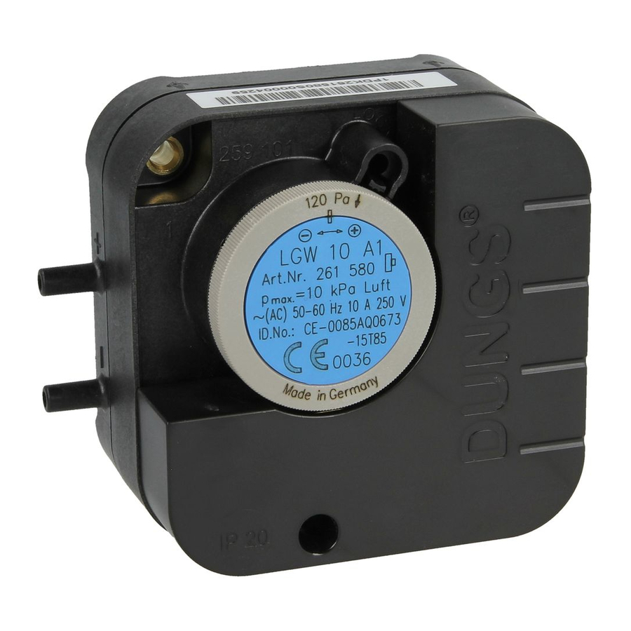
Dungs LGW A1 Series Anleitung Handbuch - Seite 5
Blättern Sie online oder laden Sie pdf Anleitung Handbuch für Schalter Dungs LGW A1 Series herunter. Dungs LGW A1 Series 12 Seiten. Differential pressure switch for air,flue gas and waste gas factory-adjusted
Auch für Dungs LGW A1 Series: Bedienung und Montageanleitung (6 seiten), Bedienung und Montageanleitung (6 seiten)

Einbaumaße / Dimensions
Cotes d'encombrement / Dimensioni [mm]
(5)
Höhe mit Berührschutz IP 20: 44 mm
Höhe mit Berührschutz IP 42: 44 mm
(1) optional Schaltpunktsicherung Zylinderschraube ø 3 x 14
(2) optional Verschlußkappe und Anschluß p 3, ø 4,6 mm
(3) Dichtfläche für O-Ring ø 4,87 x 1,8 nach DIN 3371
(4) Sackloch 8 x ø 3, 8 tief
(5) optional Montage Berührschutz Zylinderschraube ø 3x14
Height with shock protection IP 20: 44 mm
Height with shock protection IP 42: 44 mm
(1) optional switching point lock cheese head screw ø 3 x 14
(2) optional sealing cap and connection p3, ø 4.6 mm
(3) Sealing face for O-ring ø 4.87 x 1.8 to DIN 3371
(4) Blind hole 8 x ø 3.8 deep
(5) optionally Mounting of contact protection for cheese head screw ø 3x14
Einbaulage
Installation position
Position de montage
Posizione di montaggio
Typenschild beachten!
Refer to typeplate!
Respecter la plaquette de signalisation!
Attenersi alla targhetta di identificazione!
Auf vibrationsfreien Ein-
bau achten!
Optional
Sicherung der Schaltpunkteinstel-
lung mit Zylinderschraube ø 3x14
mm mit Längs- und Kreuzschlitz
5 ... 12
(1)
(2)
8,6
Ensure that the pressure
switch is installed free of
vibration!
Optional
Protection of the switching point ad-
justment by means of cheese head
screw ø 3x14 mm with longitudinal
and cross slot
44
6,9
16,2
Hauteur avec protection contre les contacts IP 20: 44 mm
Hauteur avec protection contre les contacts IP 42: 44 mm
(1) sécurisation optionnelle du point de déclenchement vis à tête cylindrique ø 3 x 14
(2) capuchon optionnel et raccord p 3, ø 4,6 mm
(3) surface d'étanchéité pour joint torique ø 4,87 x 1,8 selon DIN 3371
(4) trou borgne 8 x ø 3, profondeur 8
(5) en option : montage d'un écran de protection contre les contacts
accidentels, vis à tête cylindrique ø 3x14
Altezza protezione di contatto IP 20: 44 mm
Altezza protezione di contatto IP 42: 44 mm
(1) come optional, fissaggio del punto di commutazione mediante vite a testa cilindrica ø 3 x 14
(2) come optional, tappo di chiusura e attacco p 3, ø 4,6 mm
(3) superficie di tenuta per anello torico ø 4,87 x 1,8 a norma DIN 3371
(4) foro cieco 8 x ø 3 di profondità
(5) optional montaggio protezione dal contatto vite a testa cilindrica ø 3x14
Veiller à ce que le pres-
sostat ne subisse pas de
vibrations !
Optional
Sécurisation du réglage du point
d'enclenchement à l'aide de vis à
tête cylindrique ø 3x14 mm, fendues
et cruciformes
82
□ 72
53,75
ø 4,2
44,6
_
+
L G W 3 A1
A rt.-Nr. 261 585
p
= 10 kP a Luft
max.
-15 T85
0036
α
Evitare possibilità di
vibrazioni!
Optional
Fissaggio della regolazione del
punto d'inserzione con vite cilind-
rica di diametro ø 3x14 mm dotata
d'intaglio longitudinale e a croce
10
(3)
(4)
α
