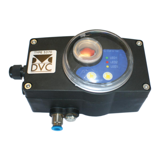
DVC 5370 Handbuch für Installation, Betrieb und Wartung - Seite 12
Blättern Sie online oder laden Sie pdf Handbuch für Installation, Betrieb und Wartung für Schalter DVC 5370 herunter. DVC 5370 16 Seiten. Mechanical limit switch with valve and led

4. 6. Circuit connection
Main voltage
Type 5370 controller could be connected with different voltage:
Power: DC24 V(standard)
AC 110V,220V (optional)
Electronic component
All of the electronic components in the control device of Type 5370 are equipped with built-in pin connectors
which avoid unnecessary wiring and interference. According to standard, a PCB could be connected with 3
solenoid valves (V1, V2, V3) at most and with 4 output of position feedback.
Default setting as follows:
Output:
156123-Displacement version
S1,S2
Output DC24V+ (standard configuration)
A +
Analog signal output 4-20mA positive electrode +
A -
Analog signal output 4-20mA negative electrode -
156133 -AS-I Bus protocol version
S1,S2, Output DC24V+ (standard configuration)
AS-INTERFACE BUS protocol communication
Input:
Signal input 24V+, control panel or PLC
V1 - the 1st solenoid valve (driving by single-acting)
Signal light:
S1 - turning on the detecting
position of valve (Green LED light)
S2 - turning off the detecting
position of valve (red LED light)
11 / 15
