- ページ 12
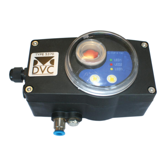
スイッチ DVC 5370のPDF インストレーション、オペレーション、メンテナンスマニュアルをオンラインで閲覧またはダウンロードできます。DVC 5370 16 ページ。 Mechanical limit switch with valve and led

4. 6. Circuit connection
Main voltage
Type 5370 controller could be connected with different voltage:
Power: DC24 V(standard)
AC 110V,220V (optional)
Electronic component
All of the electronic components in the control device of Type 5370 are equipped with built-in pin connectors
which avoid unnecessary wiring and interference. According to standard, a PCB could be connected with 3
solenoid valves (V1, V2, V3) at most and with 4 output of position feedback.
Default setting as follows:
Output:
156123-Displacement version
S1,S2
Output DC24V+ (standard configuration)
A +
Analog signal output 4-20mA positive electrode +
A -
Analog signal output 4-20mA negative electrode -
156133 -AS-I Bus protocol version
S1,S2, Output DC24V+ (standard configuration)
AS-INTERFACE BUS protocol communication
Input:
Signal input 24V+, control panel or PLC
V1 - the 1st solenoid valve (driving by single-acting)
Signal light:
S1 - turning on the detecting
position of valve (Green LED light)
S2 - turning off the detecting
position of valve (red LED light)
11 / 15
