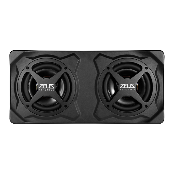
Hifonics Zeus ZRX200A Benutzerhandbuch - Seite 7
Blättern Sie online oder laden Sie pdf Benutzerhandbuch für Subwoofer Hifonics Zeus ZRX200A herunter. Hifonics Zeus ZRX200A 13 Seiten.

IMPORTANT INFORMATIONS
ZRX200A
Subwoofer ................................................................................................................................................................................20 cm (8")
Output Power RMS ....................................................................................................................................................................150 Watts
Output Power Max. ....................................................................................................................................................................300 Watts
Lowpass Filter ........................................................................................................................................................................50 - 150 Hz
Phase Shift ...................................................................................................................................................................................0°/180°
Bass Boost .................................................................................................................................................................................0 - 12 dB
Subsonic Filter ................................................................................................................................................................................ 20 Hz
Frequency Response .................................................................................................................................................................30-150 Hz
Signal to Noise Ratio ......................................................................................................................................................................>90 dB
Input Sensitivity High Level ............................................................................................................................................................... 1,0 V
Input Sensitivity Low Level ............................................................................................................................................................ 300 mV
Operating Voltage ..................................................................................................................................+12 V (9 - 15 V), negative ground
Fuse Rating ....................................................................................................................................................................................... 25 A
Dimensions (W x H x L) ...............................................................................................................................................245 x 83 x 345 mm
All Specifications are subject to change.
CUSTOMER SERVICE
In general, the assembly and installation of the sound system should be made by a trained and technically skilled specialists. If you none-
theless choose the self-assembly and you have any problems, contact your specialist dealer or the Audio Design Service Department under
Tel. +49 7253 - 94 65 92 or by E-Mail to [email protected]
IMPORTANT NOTES PRIOR TO INSTALLATION
ATTENTION: Before you start with the installation, disconnect the ground connection from the vehicle's battery in order to prevent short
circuits. This guide is an installation aid for a proper installation of the sound system. Please read the following instructions:
• This device is only suited for a 12 volt system in a vehicle with negative ground.
• The radiated heat while operation requires sufficient air circulation at the place of installation.
• Ensure the accessibility of the fuse and the operating elements after installation.
• The reliability and performance of the device depends on the quality of installation.
• Please treat all parts of the sound system and the components of your vehicle with caution.
• Follow under all circumstance the regulations of the vehicle manufacturer and do not make any modifications
on the vehicle, which could interfere the driving safety.
INSTALLATION
Choose a suitable location for your device. The permanent temperature of the location should not be lower than 5°C and not higher than
50°C. Protect the device from moisture and humidity. Ensure that your device will not get loose during the drive and hurt someone in the
passenger cabin. Use therefor the included mounting brackets (4 x) and screws (8 x). Then use self-tapping screws (not included) from the
specialist trade, to fix the device in your vehicle.
Please observe not to damage any serial components of your vehicle (air bags, wires, gas tank etc.) during the installation of your device
by drilling or any other operations.
10 ~ 90%
5 ~ 50°C
7
