Directed Xpresskit DBALL2 Installationshandbuch - Seite 3

Blättern Sie online oder laden Sie pdf Installationshandbuch für Durch Schlösser Directed Xpresskit DBALL2 herunter. Directed Xpresskit DBALL2 12 Seiten. Ford5 remote start ready (rsr) installation
Auch für Directed Xpresskit DBALL2: Installationshandbuch (19 seiten), Installationshandbuch (18 seiten), Handbuch (14 seiten), Installationshandbuch (13 seiten), Installationshandbuch (14 seiten), Installationshandbuch (19 seiten), Installationshandbuch (16 seiten), Installationshandbuch (20 seiten), Installationshandbuch (15 seiten), Handbuch für Installation und Kurzanleitung (16 seiten), Installationshandbuch (18 seiten), Installationshandbuch (16 seiten), Installationshandbuch (18 seiten), Installationshandbuch (16 seiten), Handbuch (19 seiten)
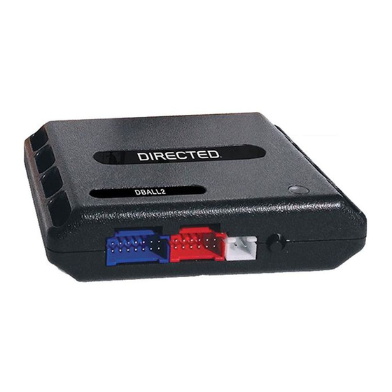
Directed Xpresskit DBALL2 Installationshandbuch
Platform: DBALL2
Firmware: MIT2
Wiring Diagram
6 Amp
diodes
(+) Parking
Lights (left):
White/Black,
1 2
pin 6
6
(-) PTS 1:
(+) PTS 2:
Yellow, pin 2
Lt. Green/Red, pin 4
1
2
3
4
5
6
7
8
9
10
Not required in D2D mode.
Tach wire is an optional connection required on some remote starters, which do not support a tach signal in D2D.
[1]
Connect Lock wire only if ignition controlled locks feature is active. This feature is configurable in your remote starter.
[2]
Unless specified otherwise, all connectors are displayed from the wire side, with the exception of the OBDII diagnostic connector.
C-417
(white conn. at
fusebox in driver dash)
(-) Hood Status Input
(+) Brake Status Input
(AC) Tach Input
[1]
(-) Trunk Status Input
(-) Door Status Input
(-) E-Brake Status Input
(+) Parking Lights Output
(+) Ignition Output
(+) Parking
Lights
(right):
Black/
(+) Ignition:
White, pin 3
Brown/Red,
pin 2
3
4
5
2
7
8
9
10
11
12 13
1
4
5
6
7
C-418
(white conn.at fusebox
C-402
in driver dash)
(white conn. at
fusebox in driver dash)
HS CAN High: Yellow, pin 6
1
9
HS CAN Low: Brown, pin 14
HS CAN 1 High: Tan/Black: 3
HS CAN 1 Low: Tan: 4
HS CAN 2 High: Orange/Green: 5
HS CAN 2 Low: Orange/Brown: 6
(+) 12V
(+) 12V: Red: 13
(-) Ground
(-) Ground: Black: 14
(-) E-Brake Status Output: Black/White: 1
(-) PTS 1 Output: Green/Black: 2
(-) Door Status Output: Green/White: 3
(-) Trunk Status Output: Red/Black: 4
(AC) Tach Output: Violet/White: 5
[1]
(+) Brake Status Output: Gray: 6
(+) PTS 2 Output: Violet/Brown: 9
(-) Hood Status Output: Blue/Red: 12
Engine Start/Stop Switch
(white conn. at PTS button)
HS CAN 2 Low: Red/White, pin 16
HS CAN 1 High: Yellow/Pink, pin 17
36
35
34
33
32
31
30
29
28
27
26
25
24
15
14
13
12
11
10
9
8
[2] (-) Lock: Gray, pin 28
(-) Lock Output
(-) Unlock Output
(-) GWR (Status)
(+) Starter Output
(-) Ground
(+) 12V
(+) 12V:
White, pin 2
3
C-410
(black conn. at
8
fusebox in driver dash)
Diagnostic connector
8
OBDII
(connector side view)
16
RF
DBALL2
Prog. Button
LED
Use only for Ignition
23
22
21
20
19
18
17
16
controlled locks feature
7
6
5
4
3
2
1
(+) Starter: Violet, pin 9
1 2
3
9
6
7
8
10
11
C-420
(white conn. at fusebox in driver dash)
C-418
C-417
10: Blue/White: (-) GWR (Status) Input
2: Blue: (-) Unlock Input
1: Green: (-) Lock Input
(+)12V
RX
(-) Ground
TX
P#: XKD2D65
© 2017 Directed. All rights reserved.
Rev.: 20170620
Page 3
.
[2]
4
5
12 13