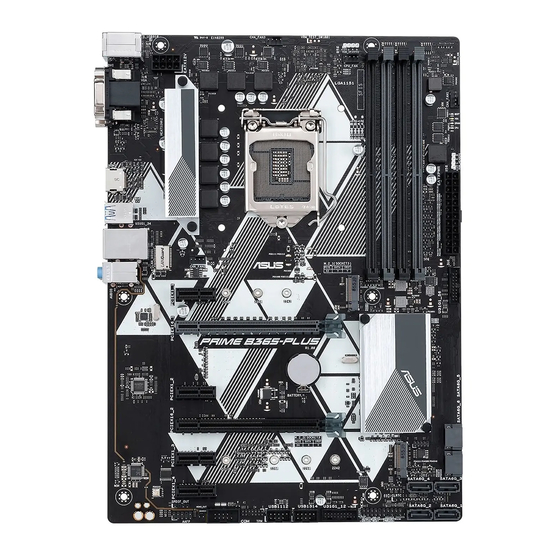
Asus 90MB11H0-M0EAY0 Manual - Página 14
Navegue en línea o descargue pdf Manual para Placa base Asus 90MB11H0-M0EAY0. Asus 90MB11H0-M0EAY0 35 páginas.

•
Reset button (2-pin RESET)
This 2-pin connector is for the chassis-mounted reset button for system
reboot without turning off the system power.
•
Chassis intrusion header (2-pin CHASSIS)
This connector is for a chassis-mounted intrusion detection sensor or switch.
Connect one end of the chassis intrusion sensor or switch cable to this
connector. The chassis intrusion sensor or switch sends a high-level signal to
this connector when a chassis component is removed or replaced. The signal
is then generated as a chassis intrusion event.
USB 2.0 connectors (10-1 pin USB1112, USB1314)
Connect a USB module cable to any of these
connectors, then install the module to a slot opening at
the back of the system chassis. These USB connectors
comply with USB 2.0 specifications and supports up to
480Mbps connection speed.
TPM connector (14-1 pin TPM)
This connector supports a Trusted Platform Module
(TPM) system, which can securely store keys, digital
certificates, passwords, and data. A TPM system
also helps enhance network security, protects digital
identities, and ensures platform integrity.
Serial port connector (10-1 pin COM)
This connector is for a serial (COM) port. Connect the
serial port module cable to this connector, then install
the module to a slot opening at the back of the system
chassis.
Mono out header (2-pin MONO_OUT)
This internal mono out header allows connection to an
internal, low power speaker for basic system sound
capability. The subsystem is capable of driving a
speaker load of 4 Ohms at 2 Watts (rms).
Chapter 1: Product introduction
USB1112
USB1314
PIN 1
PIN 1
TPM
PIN 1
COM
PIN 1
MONO_OUT
PIN 1
1-6
