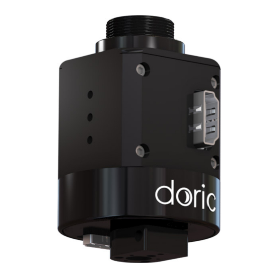
DORIC Electrical Rotary Joint Manual del usuario - Página 7
Navegue en línea o descargue pdf Manual del usuario para Equipos de grabación DORIC Electrical Rotary Joint. DORIC Electrical Rotary Joint 14 páginas.

1. Deposit the Holder ERJ frame on the base (1) and secure using #8-32 or M4 screws (2) and bolts (3) (Fig. 2.1a).
The holder can be installed in an experimental setup using 1/4 (or M6) screws and nuts.
2. Install the Electrical Rotary Joint in the Holder ERJ base (Fig. 2.1b) and secure it in place using the 3/4-32 UN secur-
ing bolt (Fig. 2.1c).
3. The 1x1 Fiber-optic Rotary Joint must first be set up in the Holder FRJ small, using the directives in the 1x1 Fiber-
optic Rotary Joint User Manual, to be installed. The Holder FRJ small is then be attached to the Holder ERJ frame (1)
using 1/4 (or M6) screws (2) and bolts (3) (Fig. 2.1d). See Figure
For installation using the 1x2 Fiber-optic Rotary Joint - Intensity division or the 1x2 Fiber-optic Rotary Joint - Wave-
length division, the rotary joint must first be installed in the Holder FRJ large using the directives in the 1x2 Fiber-
optic Rotary Joint User Manual. The Holder FRJ large is then attached to the frame in the same fashion as with an
1x1 Fiber-optic Rotary Joint. See Figure
(a) With 1x1 Fiber-optic Rotary Joint
Chapter 2. Operations Guide
2.2a
2.2b
for the final result.
(b) With 1x2 Fiber-optic Rotary Joint - Intensity
division
Figure 2.2: Holder ERJ
for the final result.
7
