- ページ 7
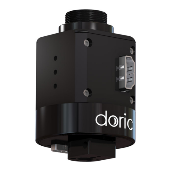
録音機器 DORIC Electrical Rotary JointのPDF ユーザーマニュアルをオンラインで閲覧またはダウンロードできます。DORIC Electrical Rotary Joint 14 ページ。

1. Deposit the Holder ERJ frame on the base (1) and secure using #8-32 or M4 screws (2) and bolts (3) (Fig. 2.1a).
The holder can be installed in an experimental setup using 1/4 (or M6) screws and nuts.
2. Install the Electrical Rotary Joint in the Holder ERJ base (Fig. 2.1b) and secure it in place using the 3/4-32 UN secur-
ing bolt (Fig. 2.1c).
3. The 1x1 Fiber-optic Rotary Joint must first be set up in the Holder FRJ small, using the directives in the 1x1 Fiber-
optic Rotary Joint User Manual, to be installed. The Holder FRJ small is then be attached to the Holder ERJ frame (1)
using 1/4 (or M6) screws (2) and bolts (3) (Fig. 2.1d). See Figure
For installation using the 1x2 Fiber-optic Rotary Joint - Intensity division or the 1x2 Fiber-optic Rotary Joint - Wave-
length division, the rotary joint must first be installed in the Holder FRJ large using the directives in the 1x2 Fiber-
optic Rotary Joint User Manual. The Holder FRJ large is then attached to the frame in the same fashion as with an
1x1 Fiber-optic Rotary Joint. See Figure
(a) With 1x1 Fiber-optic Rotary Joint
Chapter 2. Operations Guide
2.2a
2.2b
for the final result.
(b) With 1x2 Fiber-optic Rotary Joint - Intensity
division
Figure 2.2: Holder ERJ
for the final result.
7
