HID Aero X1100 Manual de instalación - Página 5
Navegue en línea o descargue pdf Manual de instalación para Controlador HID Aero X1100. HID Aero X1100 8 páginas. Intelligent controller
Powering
Trusted Identities
8.
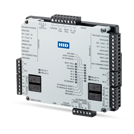
Input power, cabinet tamper, and UPS fault input wiring
The X1100 requires 12-24 V DC power. Connect power
with minimum of 18 AWG wire.
Connect the power ground to earth ground in only
ONE LOCATION within the system. Multiple earth
ground connections may cause ground loop problems
and is not advised.
Observe POLARITY on 12-24 V DC input.
Connect the AC FAIL and BATT FAIL inputs to the
corresponding contacts provided on the power supply.
Connect the TAMPER input to a tamper switch on the
enclosure.
Bulk erase configuration memory
The bulk erase function can be used for the following:
Erase all configuration and cardholder database (sanitize board, less third party applications).
Recover from database corruption causing X1100 board to continuously reboot.
Note: If clearing the memory does not correct the initialization problem, contact technical support.
Bulk erase steps
1. Set DIP switches 1 and 2 to ON, and 3 and 4 to OFF.
2. Apply power to the X1100 board.
3. LED ONLINE is on for about 15 seconds while the X1100 boots up.
4. Change DIP switches 1 or 2 to OFF within 10 seconds, after LEDs ONLINE and HOST COMM and LEDs IO INTERNAL
and IO PORT 1 start flashing alternately at a rate of 0.5 seconds.
Note: If these switches are not changed, the X1100 board will power up using the OEM default communication
parameters.
5. LED HOST COMM will flash, indicating that the configuration memory is being erased.
Note: Full memory erase takes up to 60 seconds.
6. When complete, only LEDs ONLINE and IO PORT 1 will flash for about 3 seconds.
7. The X1100 board will complete its initialization two seconds after LEDs ONLINE & IO PORT 1 stop flashing.
CAUTION: Do not remove power during the bulk erase process.
IT security
Ensure that the X1100 is installed securely. Create user
accounts to the web configuration page using secure
passwords.
Ensure that all DIP switches are in the OFF position for the
normal operating mode.
After powering up the X1100 and connecting Ethernet,
connect to the X1100 configuration manager by opening a
browser and connecting to 192.168.0.251.
The X1100 is shipped with a default login account, which
is enabled when DIP 1 is moved from OFF to ON (See step
6. DIP switch configuration). The default login User Name
(admin) and Password (password) will be available for
five minutes once the DIP switch is toggled. It is therefore
important that at least one user account is defined, and
the DIP switches are set to OFF before the X1100 is
commissioned.
Configuring the X1100 with an IP address that is accessible
from the public Internet is not recommended.
PLT-04233, Rev. A.3
HID Aero™ X1100 Installation Guide
TAMPER, AC FAIL, and BATT FAIL connections are
identical to inputs IN 1 to IN 4 and can be configured
as unsupervised or supervised. See step 7. Input circuit
wiring.
The following options are available to improve network
security:
Disable SNMP.
Disable Zeroconf discovery.
Disable the web configuration module.
Enable data encryption over the host
communication port.
5