Digitrax BXP88 Manual de instrucciones - Página 12
Navegue en línea o descargue pdf Manual de instrucciones para Sensores de seguridad Digitrax BXP88. Digitrax BXP88 16 páginas.

LED for DS2 or DS6
LED for DS1 or DS5
10.3 Panel Indicator Wiring
You can build a display panel with a track schematic and LEDs to indicate track
occupancy by connecting LEDs to the LT5 compatible output connectors on the
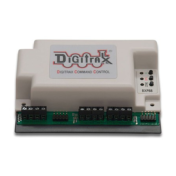
BXP88. For a panel display of occupancy status made up with user supplied
LEDs, connect to the four 0.1" 2x5 headers, and wire up high brightness LEDs
as shown in Figure 3: LED Panel Indicators Wiring. The plugs and ribbon cable
included in the Digitrax SDCK Signal Driver Cable Kit can be used.
Figure 3: LED Panel Indicators Wiring
The BXP88 incorporates current setting resistors to set the LT5 LED current typi-
cally to about 1~3mA. If you need higher LED drive currents you can use external
transistors etc. to amplify the LED current.
The LT5 header drive from the BXP88 is active high at about +3.5 volts, via a
1 Kohm resistor. Note that the ribbon cable includes separate ground return
conductors for each LED that allow a 10 conductor ribbon cable to be split into 5
pairs to conveniently routed to individual LEDS. Be sure to connect the +ve active
detection section output wires to the LED anodes. Do not connect any LT5 wiring
to other voltages as this may cause damage and void the warranty.
© 2017 Digitrax, Inc.
Figure 2: LT5 Tester
LED for DS3 or DS7
Ribbon Cable and Plug
— 12 —
LED for DS4 or DS8
Zone Power LED
Zone Power
DS1 or DS5
DS2 or DS6
DS3 or DS7
DS4 or DS8
www.digitrax.com
