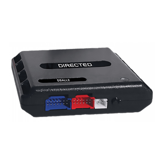
Directed Electronics Xpresskit DBALL Manual de instalación - Página 5
Navegue en línea o descargue pdf Manual de instalación para Accesorios para automóviles Directed Electronics Xpresskit DBALL. Directed Electronics Xpresskit DBALL 14 páginas. Databus all combo bypass module
También para Directed Electronics Xpresskit DBALL: Manual de instalación (14 páginas)

Platform: DBALL
Firmware: GM5
Installation Type 2
Black Connector located at the
ignition switch (this connector
can have 5 or 6 pin).
Red/White
Connect these
wires only if the
vehicle is equipped
with PK3+.
Driver Door
Sense Trigger
You need to connect these
wires together. These
connections are required for
the module work properly.
Connector C2
Not required in D2D mode.
The Mobile Integration Systems
BCM Side
Key Side
6
5
4
3
R. Code
White, Pink
or Pink/black
1: Light Green: Single Wire CAN
7: Brown
8: Yellow: R. Code (Car Side)
9: Orange/Yellow: R. Code (Key Side)
10: Orange/Red: (+) 12v (Car Side)
11: Yellow/Red: (+) 12v (Connector Side)
(+) 12v
13: Red: (+) 12v
(-) Ground
14: Black: (-) Ground
1: Black/White: RAP OFF
3: Green/White: (-) Door Status Output
4: Red/Black: (-) Trunk Status Output
5: Violet/White: (AC) Tach Output
6: Gray: (+) Brake Status Output
8: Violet/Green: R. Code (Car Side)
9: Violet/Brown
10: Yellow/Black: Keyless Data
PIN 12
Connector C2
of the BCM
BCM is located in the center console.
Exception: in Pontiac Solstice and Saturn Sky: located under the carpet,
BCM
C2
Vehicle CAN Bus Integration System
(+) Brake Status Input
(AC) Tach Input
(-) Trunk Status Input
(-) Door Status Input
(+) Accessory Output
(+) Ignition Output
Green or Black
connector located
at the ignition switch.
2
1
The position of the R. Code wire may vary.
Test this wire using the following chart:
- 12V at Key Input
- 4.3V at Ignition
- 0V at Accessory
- 3V at Start
RF Loop Connector
Programming button
DBALL
LED
Rev.: 20101103
Hood Switch
Parking Lights
(+) 12 V Input
Ground
(-) Lock Output
(-) Unlock Output
(-) Trunk Release Output
(+) Starter Output
(+) Ignition Output
(-) GWR (Status)
1
8
9
16
Diagnostic connector
OBDII (connector side view)
10: Blue/White: (-) GWR (Status) Input
9: Pink: (+) Ignition Input
8: Violet: (+) Starter Input
Trunk Release Input
3: Red/White: (-)
2: Blue: (-) Unlock Input
1: Green: (-) Lock Input
(+)12v
RX
(-) Ground
TX
P#: XKD2D65
passenger side
firewall.
© 2010 Directed Electronics. All rights reserved.
Page 5
