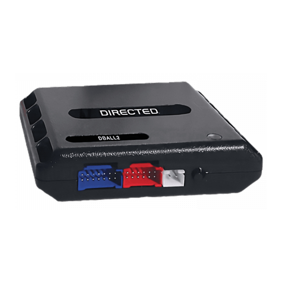
Directed Electronics Xpresskit DBALL Manual de instalación - Página 7
Navegue en línea o descargue pdf Manual de instalación para Accesorios para automóviles Directed Electronics Xpresskit DBALL. Directed Electronics Xpresskit DBALL 14 páginas. Databus all combo bypass module
También para Directed Electronics Xpresskit DBALL: Manual de instalación (14 páginas)

Platform: DBALL
Firmware: GM5
Installation Type 4
Driver Door
Sense Trigger
You need to connect these
wires together. These
connections are required for
the module work properly.
* If applicable - see the Function List.
Not required in D2D mode.
The Mobile Integration Systems
Hood Switch
(+) Brake Input
BCM Side
Key Side
6
5
4
3
White or White/Blue
2: Purple/Yellow: J1850
7: Brown
8: Yellow: R. Code (Car Side)
9: Orange/Yellow: R. Code (Key Side)
(+) 12v
13: Red: (+) 12v
(-) Ground
14: Black: (-) Ground
1: Black/White: RAP OFF
3: Green/White: (-) Door Status Output*
5: Violet/White: (AC) Tach Output
8: Violet/Green: R. Code (Car Side)
9: Violet/Brown
(AC) Tach Input
(-) Door Status Input*
(+) Accessory Output
(+) Ignition Output
2
1
Green or Black Connector
located at the ignition switch.
RF Loop Connector
Programming button
DBALL
LED
Vehicle CAN Bus Integration System
Parking Lights
(+) 12 V Input
Ground
(-) Lock Output*
(-) Unlock Output*
(+) Starter Output
(+) Ignition Output
(-) GWR (Status)
1
8
9
16
Diagnostic connector
OBDII (connector side view)
10: Blue/White: (-) GWR (Status) Input
9: Pink: (+) Ignition Input
8: Violet: (+) Starter Input
2: Blue: (-) Unlock Input*
1: Green: (-) Lock Input*
(+)12v
RX
(-) Ground
TX
P#: XKD2D65
© 2010 Directed Electronics. All rights reserved.
Rev.: 20101103
Page 7
