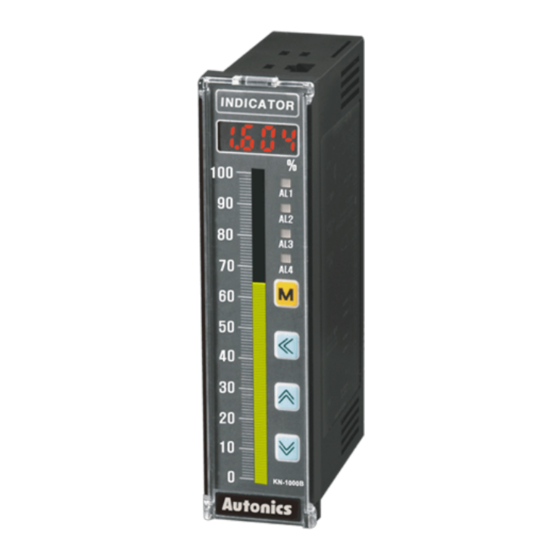
Autonics KN-1000B Series Manuel du produit - Page 2
Parcourez en ligne ou téléchargez le pdf Manuel du produit pour {nom_de_la_catégorie} Autonics KN-1000B Series. Autonics KN-1000B Series 6 pages. Bar graphic temperature indicators

Ordering Information
This is only for reference, the actual product does not support all combinations.
For selecting the specified model, follow the Autonics website .
K
N
-
1
❶ Alarm output
❷ Option output
0: No mark
0: No mark
2: 2 alarm
1: PV Transmission
4: 4 alarm
4: Communication
Product Components
• Product
• Instruction manual
• Unit sticker ×1
• Connector ( KN-10□□B: ×3, KN-12□□B: ×4,
Software
Download the installation file and the manuals from the Autonics website.
■ DAQMaster
DAQMaster is comprehensive device management program. It is available for
parameter setting, monitoring.
Specifications
KN-1000B Series
Series
AC voltage
Power supply
100 - 240 VACᜠ 50/60 Hz
Allowable voltage range
90 to 110% of rated voltage
Power consumption
≤ 6 VA
Sampling period
• Thermocouple, RTD: 250 ms • Analog: 100 ms
Input specification
Refer to 'Input Type and Using Range'.
Contact
• ON: ≤ 2 kΩ • OFF: ≥ 90 kΩ
Digital
Non contact
• Residual voltage: ≤ 1.0 V • leakage current: ≤ 0.03 mA
input
Outflow current ≈ 0.2 mA
Alarm
• 2 point relay: 250 VACᜠ 3 A 1c • 4 point relay: 250 VACᜠ 1 A 1a
Option
PV transmission ISOLATED DC 4-20 mA (Load resistance: ≤ 600 Ω)
output
RS485 comm.
Modbus RTU
Display type
7 Segment (red), Graph bar (green)
Alarm output Hysteresis
1 to 999 digit
• 2 point: ≥ 10,000,000 operations
Mechanical
• 4 point: ≥ 20,000,000 operations
Relay life
cycle
• 2 point: ≥ 100,000 operations (load resistance: 250 VACᜠ 3 A)
Electrical
• 4 point: ≥ 500,000 operations (load resistance: 250 VACᜠ 1 A)
Between input terminal and power terminal: 2,000 VACᜠ 50/60
Dielectric strength
Hz for 1 min
0.75 mm amplitude at frequency of 5 to 55 Hz (for 1 min) in each X,
Vibration
Y, Z direction for 2 hours
Insulation resistance
≥ 100 MΩ (500 VDCᜡ megger)
Noise immunity
±2 kV square shaped noise (pulse width 1 ㎲) by noise simulator
Memory retention
≈ 10 years (non-volatile semiconductor memory type)
Ambient temperature
-10 to 50 ℃, storage: -20 to 60 ℃ (no freezing or condensation)
35 to 85%RH, storage: 35 to 85%RH (no freezing or condensation)
Ambient humidity
Approval
ᜢ ᜫ
Unit weight (packaged)
≈ 182 g (≈ 304 g)
Communication Interface
■ RS485
Comm. protocol
Modbus 1.1 RTU
Maximum connection
32 units
Synchronous method
Asynchronous
Comm. method
Two-wire half duplex
Comm. effective range
≤ 1,200 m (≤ 700 m recommended)
Comm. speed
9,600 (default) / 4,800 / 2,400 / 1,200 (parameter)
Data bit
8 bit (fixed)
Parity bit
None (fixed)
Stop bit
1 bit (fixed)
❶
❷
❸
B
❸ Power supply
0: 100-240 VACᜠ 50/60 Hz
1: 24 VDCᜡ
• Bracket ×2
KN-140□B: ×4, KN-141□B: ×5, KN-144□B: ×5)
DC voltage
24 VDCᜡ
≤ 4 W
Input Type and Using Range
Input type
K (CA)
K (CA)
J (IC)
E (CR)
T (CC)
B (PR)*
Thermo-
R (PR)
couple
S (PR)*
N (NN)*
C (W5)*
L (IC)*
U (CC)*
Platinel II*
Cu50Ω*
Cu100Ω*
RTD
JPt100Ω
DPt50Ω
DPt100Ω
0.00 - 20.00 mA
Current
4.00 - 20.00 mA
-50.0 - 50.0 mV
Analog
-199.9 - 200.0 mV
Voltage
-1.000 - 1.000 V
-1.00 - 10.00 V
• Above input types which have the * mark are displayed only in Input specification expansion. Refer to 'Mode
Setting' to check how to enter the mode.
■ Display accuracy
Input type
Using temperature Display accuracy
At room temperature
Thermocouple
(25 ℃ ±5 ℃)
RTD
Out of room
Analog
temperature range
• In case of TC-T, TC-U, ±2.0 ℃ will be added to the degree standard.
Unit Descriptions
7
1
2
3
8
4
6
5
Back
Front
8. Selection switch for input specification
0 - 20 mA: Select it for DC 0 (4) - 20 mA input (default)
-1 - 10 V: Select it for -1 - 10 VDCᜡ input
RTD / TC / mV / ±1 V: Select it for Thermocouple, RTD, ±1 V, mV input
• The setting of input type selection switch and the setting value of input type parameter
should be same and it can display the proper measurement value.
Display
Using range (℃)
Using range (℉)
200 to 1350
TcK1
-199.9 to 999.9
TcK2
-199.9 to 800.0
TC-J
-199.9 to 800.0
TC-E
-199.9 to 400.0
-199.9 to 752.0
TC-T
100 to 1,800
TC-B
0 to 1,750
TC-R
0 to 1,750
TC-S
-200 to 1,300
TC-N
0 to 2,300
TC-C
-199.9 to 900.0
TC-L
-199.9 to 400.0
-199.9 to 752.0
TC-U
0 to 1,390
TC-P
-199.9 to 200.0
-199.9 to 392.0
Cu50
-199.9 to 200.0
-199.9 to 392.0
Cu10
-199.9 to 600.0
JPt1
-199.9 to 600.0
DPt5
-199.9 to 850.0
DPt1
aMA1
-1,999 to 9,999
aMA2
( Display range is variable according to
aMV1
decimal point position.)
aMV2
A-V1
A-V2
PV ±0.2% F.S. ±1 digit
• Thermocouple below -100 ℃: (PV ±0.4% F.S.) ±1digit
PV ±0.3% F.S. ±1 digit
1. Display part(red)
Run mode: Displays PV (Present value).
Setting mode: Displays parameter and setting
value.
2. Unit sticker part
3. Alarm output indicator
Turns ON when the alarm output is ON.
4. [M] key
Used to enter parameter set mode, move to
parameters, save SV and return to RUN mode.
5. [◀], [▲], [▼] key
Used to enter and change parameter setting value.
6. Bar graph (green)
Refer to 'Bar Graph'.
7. Space for recognizing device by user
-328 to 2,462
-328 to 1,832
-328 to 1,472
-328 to 1,472
212 to 3,272
32 to 3,182
32 to 3,182
-328 to 2,372
32 to 4,172
-328 to 1,652
32 to 2,534
-328 to 1,112
-328 to 1,112
-328 to 1,530
