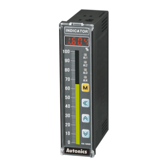
Autonics KN-1000B Series Manuale del prodotto - Pagina 2
Sfoglia online o scarica il pdf Manuale del prodotto per Strumenti di misura Autonics KN-1000B Series. Autonics KN-1000B Series 6. Bar graphic temperature indicators

Ordering Information
This is only for reference, the actual product does not support all combinations.
For selecting the specified model, follow the Autonics website .
K
N
-
1
❶ Alarm output
❷ Option output
0: No mark
0: No mark
2: 2 alarm
1: PV Transmission
4: 4 alarm
4: Communication
Product Components
• Product
• Instruction manual
• Unit sticker ×1
• Connector ( KN-10□□B: ×3, KN-12□□B: ×4,
Software
Download the installation file and the manuals from the Autonics website.
■ DAQMaster
DAQMaster is comprehensive device management program. It is available for
parameter setting, monitoring.
Specifications
KN-1000B Series
Series
AC voltage
Power supply
100 - 240 VACᜠ 50/60 Hz
Allowable voltage range
90 to 110% of rated voltage
Power consumption
≤ 6 VA
Sampling period
• Thermocouple, RTD: 250 ms • Analog: 100 ms
Input specification
Refer to 'Input Type and Using Range'.
Contact
• ON: ≤ 2 kΩ • OFF: ≥ 90 kΩ
Digital
Non contact
• Residual voltage: ≤ 1.0 V • leakage current: ≤ 0.03 mA
input
Outflow current ≈ 0.2 mA
Alarm
• 2 point relay: 250 VACᜠ 3 A 1c • 4 point relay: 250 VACᜠ 1 A 1a
Option
PV transmission ISOLATED DC 4-20 mA (Load resistance: ≤ 600 Ω)
output
RS485 comm.
Modbus RTU
Display type
7 Segment (red), Graph bar (green)
Alarm output Hysteresis
1 to 999 digit
• 2 point: ≥ 10,000,000 operations
Mechanical
• 4 point: ≥ 20,000,000 operations
Relay life
cycle
• 2 point: ≥ 100,000 operations (load resistance: 250 VACᜠ 3 A)
Electrical
• 4 point: ≥ 500,000 operations (load resistance: 250 VACᜠ 1 A)
Between input terminal and power terminal: 2,000 VACᜠ 50/60
Dielectric strength
Hz for 1 min
0.75 mm amplitude at frequency of 5 to 55 Hz (for 1 min) in each X,
Vibration
Y, Z direction for 2 hours
Insulation resistance
≥ 100 MΩ (500 VDCᜡ megger)
Noise immunity
±2 kV square shaped noise (pulse width 1 ㎲) by noise simulator
Memory retention
≈ 10 years (non-volatile semiconductor memory type)
Ambient temperature
-10 to 50 ℃, storage: -20 to 60 ℃ (no freezing or condensation)
35 to 85%RH, storage: 35 to 85%RH (no freezing or condensation)
Ambient humidity
Approval
ᜢ ᜫ
Unit weight (packaged)
≈ 182 g (≈ 304 g)
Communication Interface
■ RS485
Comm. protocol
Modbus 1.1 RTU
Maximum connection
32 units
Synchronous method
Asynchronous
Comm. method
Two-wire half duplex
Comm. effective range
≤ 1,200 m (≤ 700 m recommended)
Comm. speed
9,600 (default) / 4,800 / 2,400 / 1,200 (parameter)
Data bit
8 bit (fixed)
Parity bit
None (fixed)
Stop bit
1 bit (fixed)
❶
❷
❸
B
❸ Power supply
0: 100-240 VACᜠ 50/60 Hz
1: 24 VDCᜡ
• Bracket ×2
KN-140□B: ×4, KN-141□B: ×5, KN-144□B: ×5)
DC voltage
24 VDCᜡ
≤ 4 W
Input Type and Using Range
Input type
K (CA)
K (CA)
J (IC)
E (CR)
T (CC)
B (PR)*
Thermo-
R (PR)
couple
S (PR)*
N (NN)*
C (W5)*
L (IC)*
U (CC)*
Platinel II*
Cu50Ω*
Cu100Ω*
RTD
JPt100Ω
DPt50Ω
DPt100Ω
0.00 - 20.00 mA
Current
4.00 - 20.00 mA
-50.0 - 50.0 mV
Analog
-199.9 - 200.0 mV
Voltage
-1.000 - 1.000 V
-1.00 - 10.00 V
• Above input types which have the * mark are displayed only in Input specification expansion. Refer to 'Mode
Setting' to check how to enter the mode.
■ Display accuracy
Input type
Using temperature Display accuracy
At room temperature
Thermocouple
(25 ℃ ±5 ℃)
RTD
Out of room
Analog
temperature range
• In case of TC-T, TC-U, ±2.0 ℃ will be added to the degree standard.
Unit Descriptions
7
1
2
3
8
4
6
5
Back
Front
8. Selection switch for input specification
0 - 20 mA: Select it for DC 0 (4) - 20 mA input (default)
-1 - 10 V: Select it for -1 - 10 VDCᜡ input
RTD / TC / mV / ±1 V: Select it for Thermocouple, RTD, ±1 V, mV input
• The setting of input type selection switch and the setting value of input type parameter
should be same and it can display the proper measurement value.
Display
Using range (℃)
Using range (℉)
200 to 1350
TcK1
-199.9 to 999.9
TcK2
-199.9 to 800.0
TC-J
-199.9 to 800.0
TC-E
-199.9 to 400.0
-199.9 to 752.0
TC-T
100 to 1,800
TC-B
0 to 1,750
TC-R
0 to 1,750
TC-S
-200 to 1,300
TC-N
0 to 2,300
TC-C
-199.9 to 900.0
TC-L
-199.9 to 400.0
-199.9 to 752.0
TC-U
0 to 1,390
TC-P
-199.9 to 200.0
-199.9 to 392.0
Cu50
-199.9 to 200.0
-199.9 to 392.0
Cu10
-199.9 to 600.0
JPt1
-199.9 to 600.0
DPt5
-199.9 to 850.0
DPt1
aMA1
-1,999 to 9,999
aMA2
( Display range is variable according to
aMV1
decimal point position.)
aMV2
A-V1
A-V2
PV ±0.2% F.S. ±1 digit
• Thermocouple below -100 ℃: (PV ±0.4% F.S.) ±1digit
PV ±0.3% F.S. ±1 digit
1. Display part(red)
Run mode: Displays PV (Present value).
Setting mode: Displays parameter and setting
value.
2. Unit sticker part
3. Alarm output indicator
Turns ON when the alarm output is ON.
4. [M] key
Used to enter parameter set mode, move to
parameters, save SV and return to RUN mode.
5. [◀], [▲], [▼] key
Used to enter and change parameter setting value.
6. Bar graph (green)
Refer to 'Bar Graph'.
7. Space for recognizing device by user
-328 to 2,462
-328 to 1,832
-328 to 1,472
-328 to 1,472
212 to 3,272
32 to 3,182
32 to 3,182
-328 to 2,372
32 to 4,172
-328 to 1,652
32 to 2,534
-328 to 1,112
-328 to 1,112
-328 to 1,530
