Miller 1025 Manuel de l'opérateur - Page 3
Parcourez en ligne ou téléchargez le pdf Manuel de l'opérateur pour {nom_de_la_catégorie} Miller 1025. Miller 1025 13 pages. Fluid head

Introduction
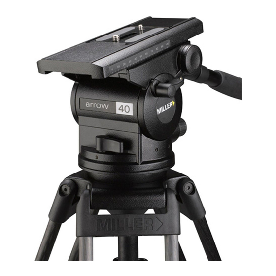
Thank you for purchasing the Arrow 40/55 Fluid Head. The
Arrow 40 Fluid Head has been designed to suit payload
capacities from ENG to standard configuration EFP cameras.
The Arrow 55 Fluid Head has been designed to suit EFP and
Studio cameras.
The robust design and construction of the Arrow 40/55 Fluid
Head offers maximum stability, accuracy and durability and
includes precision ball bearing mounted Fluid Drag Plate
system in the Pan and Tilt assembly to deliver true fluid drag
performance over the entire temperature and payload range.
The Fluid Drag and the Counterbalance system were
designed to provide excellent control and repeatability and
offer progressive equal increments of drag and torque.
The Arrow 40/55 Fluid Head also offers Illuminated single
control location for operating Pan/Tilt, Counterbalance and
viewing Bubble level.
The Arrow 40/55 Fluid Head will give best performance when
used on a wide range of Miller tripods, including SOLO ENG
(#1505), Sprinter II (#1589, #1580, #1576) and HD (#931)
tripod. This will ensure maximum system stability to suit any
professional set-up. The Arrow 40/55 Fluid Head will suit
most industry standard 100 mm tripods as well, please refer
to manufactures' manual for mounting details.
Safety Instructions
Attaching/removing the camera
Please use this manual to familiarise yourself with the operation
of the Arrow 40/55 Fluid Head and observe these instructions
to prevent any damage to your equipment. Ensure that all
equipment is operating correctly and free from defects and
damage, also please ensure that the tripod is steady, secure
and that the bowl is approximately horizontal when attaching
the camera. The operator is responsible for the safe operation
of this piece of equipment.
Do not exceed the maximum payload capacity of the Fluid
◗
Head.
Do not leave the camera unattended on the Fluid Head.
◗
Do not release the SLIDING PLATFORM LOCK whilst the
◗
camera is at an angle.
Do not adjust the tripod whilst the camera is attached to
◗
the Fluid Head.
Ensure PAN HANDLE CLAMP and CLAMP NUT is securely
◗
tightened.
Apply TILT LOCK when adding/removing equipment from
◗
the camera or when attaching/removing the camera from
the Fluid Head.
Hold camera securely whilst changing Counterbalance,
◗
Pan Drag or Tilt Drag settings.
Hold the camera securely whilst releasing the QUICK
◗
RELEASE KNOB.
Hold camera securely whilst adjusting the CLAMP NUT to
◗
level the Fluid Head.
2
