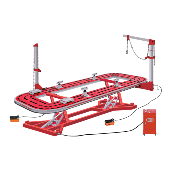
Dato CRMPL 201 Panduan Pengoperasian - Halaman 5
Jelajahi secara online atau unduh pdf Panduan Pengoperasian untuk Aksesori Mobil Dato CRMPL 201. Dato CRMPL 201 14 halaman. Auto body collision repair system

may develop the subjectivity of operators and supply more convenience. These are 17
pieces of pulling tools。
ATTENTION: When operation, do not exceed the Max Load capacity as far as the data in
table 3 are concerned. The manufacturer has the right to change the quantity and model of
pulling tools.
2) Dolly for wheel
The dolly for wheel is used to move the accident vehicle whose wheel is break.
Ⅱ Loading and Unloading
Platf or m Lengt h
Platf or m width
Working height
Capacity
1. Attentions during transportation
a) The truc k loading capac it y must be min. 3. 5 tons.
b) During tr ansport ation, the equipment is not allow ed to cont act tr uck floor,
ther e must be woodblock under it .
c) The equipment mus t be fixed dur ing tr ansport ation.
d) The movable components (f or example tow er) must be fixed dur ing
tr ansport ation.
e) Never place sharp it ems or object s on the upper sur f ace of the equipment to
pr ot ect the paint .
f) Do not load the equipment with inf lammables or corr osives .
g) Prev ent equipment from rain or get ting wet .
2. Loading and Unloading
Use eit h er cr ane or fo rk lif t to load and un load th e equip men t . When using cr ane,
the steel wires pos it ions must be ev enly deployed ar ound the plat f orm to get
balance; when using for klif t , the lif ting capabilit y must be at least 5 tons, and
place the for ks to maxim um dist ance. The lengt h of for ks should be at least 1. 6
meter s and us e ex tensions if lengt h is not enough. The forks must be insert ed
under the plat f orm at balancing pos it ions width ways.
Ⅲ Installation
1. Space requirement
Min. 4m ×7m smooth cem ent gr ound is required equipped.
2. Placement of equipment
Move the plat for m to pr oper pos it ion, leave enough space bet w een the plat f orm
edges and walls to allow tower movement and repair ac cess.
3. Installation of tower chains
Insert the chain end without hook thr ough the collar pulley upw ardly, and then
thr ough the tower head. Loc k it by tower head lock (F igure 3- 1, 3- 2)
5600mm
2112mm
0- 380 -1080mm
3500K G
3
