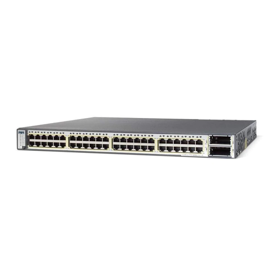
Cisco Catalyst 3750-E Series Panduan Memulai - Halaman 21
Jelajahi secara online atau unduh pdf Panduan Memulai untuk Perangkat Keras Jaringan Cisco Catalyst 3750-E Series. Cisco Catalyst 3750-E Series 27 halaman. Switches and power supply modules
Juga untuk Cisco Catalyst 3750-E Series: Panduan Memulai (33 halaman), Buletin Dukungan Produk (6 halaman), Buletin Dukungan Produk (5 halaman), Buletin Dukungan Produk (6 halaman), Catatan Instalasi (20 halaman)

Install and Connect to Devices in the 10-Gigabit Ethernet Slots
The switch 10-Gigabit Ethernet module slots are used for connections to other switches and routers.
The module slots operate in full-duplex mode and use the hot-swappable Cisco X2 transceiver modules
and the Cisco TwinGig Converter Module. The X2 transceiver modules have SC connectors to connect
to multimode fiber (MMF) and single-mode fiber (SMF) cables. The Cisco converter modules have two
SFP-module slots that convert the 10-Gigabit interface into a dual SFP interface.
When installing a transceiver module or the Cisco TwinGig Converter Module in the upper 10-Gigabit
Ethernet module slot (slot 1), position the module face up. When using the lower module slot (slot 2),
position the module face down.
When you install or remove the Cisco TwinGig converter module, the mode on the switch changes
from 10-Gigabit Ethernet to Gigabit Ethernet or the reverse. During this mode change, data traffic on
the other switch uplink ports (X2 transceiver or SFP module ports) might temporarily stop. When you
install or remove an X2 transceiver or SFP modules, traffic delay does not occur.
Use only Cisco X2 transceiver modules, Cisco converter modules, and Cisco SFP modules with the
switch. Each Cisco module has an internal serial EEPROM that is encoded with security information.
This encoding provides a way for Cisco to identify and validate that the module meets the
requirements for the switch.
Verify Port Connectivity
After you connect a device to the switch port, the port LED turns amber while the switch establishes
a link. This process takes about 30 seconds. Then the LED turns green when the switch and the
attached device have an established link. If the LED is off, the device might not be turned on, there
might be a cable problem, or there might be a problem with the adapter installed in the device. See the
"In Case of Difficulty" section on page 22 for information about online assistance.
4 5
4 6
4 7
4 8
47 X
49
X 2- 1
X 2- 2
51
t 3 7 5 0 -E
48 X
S E R IE S
P o E -4 8
50
52
21
