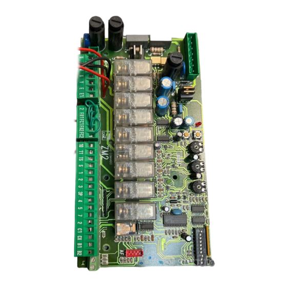
2
COLLEGAMENTO PER
ANSCHLUSSE FÜR
A
- Coordinare il senso
- Match the directions in
which gear motors A and B
di marcia dei motori-
duttori A e B, modifi-
rotate by changing the di-
rection in which motor B ro-
cando la rotazione del
motore B;
tates ;
- Stabilire tra A e B il
- Set the master (or pilot)
motore master (o pi-
motor between A and B by
lota), posizionare il
setting dip-switch 14 to ON
dip-switch 14 in ON
on the control board. "Mas-
sulla scheda coman-
ter" refers to the motor that
controls both the gates. On
do. Per "master" s'in-
tende il motore che
the control board of the 2
motor, set dip-switch 11 to
comanda ambedue i
cancelli, mentre sulla
ON to make it the "slave"
(Fig.1).
scheda comando del
2° motore posiziona-
-Make sure that the radio
re il dip 11 in ON per
receiver is activated only on
renderlo pilotato (sla-
the MASTER board Fig.2;
ve-Fig.1).
-Wire the electrical con-
- Assicurarsi che sia
nections and the normally
inserito il ricevitore
used selections only on the
radio solo sul quadro
MASTER terminal board
MASTER (Fig.2);
Fig.3;
-Eseguire solo sulla
-Wire the electrical con-
morsettiera MASTER
nections between the termi-
nal boards, as shown in the
i collegamenti elettri-
ci e le selezioni predi-
«figure A», and make sure
that the automatic closing
sposte normalmente
(Fig.3);
function is enabled for the
"master" motor and disabled
- Eseguire tra le mor-
settiere i collegamen-
for 2
- Make sure that all the dip-
ti come da «figura A»,
e accertarsi che la
switches on the board of the
chiusura automatica
2
sia attivata nel moto-
for dip 11 (Fig.4).
re "master" e disatti-
Important: set the motor's
stop limits so that the MAS-
vata nel 2° motore;
-Assicurarsi che tutti i
TER motor's door reaches
closing position after the
dip del quadro del 2°
motore siano disatti-
SLAVE motor's door.
vati (OFF) tranne il dip
11 (Fig.4).
Importante: regolare
i finecorsa dei motori
in modo che, l'anta
del motore MASTER
arrivi in chiusura dopo
della SLAVE.
-
MOTORI ABBINATI
CONNECTIONS FOR
2
PARALLELGESCHALTETEN MOTOREN
-Coordonnerle le sens
de
motoreducteurs A et
B en modifiantle sens
de rotation du moteur
B;
-Fixer entre A et B le
moteur master (ou pi-
lote) en positionnant
le dip-switch 14 sur
ON sur la fiche com-
nd
mande. Par "master"
il s'agit du moteur qui
commande les deux
grilles, tandis que sur
la fiche de comman-
de du 2sd moteur po-
sitionner le dip 11 sur
ON pour qu'il soit pi-
loté (slave - Fig.1).
-S'assurer que tous
les récepteur radio est
bien introduit seule-
ment sur le pupitre
MASTER (Fig.2);
-Effecteur seulement
sur la barrette de con-
nexion MASTER les
liaisons électriques et
les sélections normal-
nd
motor;
ment prédisposées
(Fig.3);
-Effectuer
nd
motor are (OFF), except
branchements entre
les plaques à bornes
de la façon indiquée
sur la «figure A», et
contrôler que la fonc-
tion de fermeture au-
tomatique est activée
pour le moteur "mas-
ter" et désactivée pour
le 2ème moteur.
-S'assurer que tous
les dip du pupitre du
2sd moteur sont
éteints
l'exception du dip 11
(Fig.4).
Important: régler les
interrupteurs de fin de
course des moteurs
pour que la porte du
moteur
(principal) arrive en
fermeture après celle
SLAVE (auxiliaire).
ZBKS
2
COMBINED MOTORS CONNEXIONS POUR
-
CONEXIÓN PARA
-Die Gangrichtung der Ge-
triebemotoren A und B durch
marche
des
Drehrichtu- ngsõnderung
des Motores B koordinieren;
-Legen Sie fest, welcher der
Motoren A und B der Master-
Motor (übergeordnet) sein
soll. Stellen Sie dazu den
Dip-Switch 14 auf der Steu-
erungskarte auf ON. Unter
Master-Motor wird der Mo-
tor verstanden, der beide
Tore steuert. Auf der Steue-
rungskarte des anderen Mo-
tors muß der Dip-Switch 11
auf ON gestellt werden, so
daß er eine untergeordnete
Funktion (Slave-Motor)
bekommt (Abb.1).
-Kontrollieren Sie, daß der
Radioempfänger nur auf der
MASTER-Schalttafel einge-
steckt ist (Abb.2);
-Führen Sie nur am MAS-
TER Klemmbrett die elektri-
schen Anschlüsse und die
normalerweise durchgeführ-
ten Voreinstellungen aus
(Abb.3);
- Die Verbindungen zwisch-
en den beiden Klemmleisten
der «Abbildung A»
les
entsprechend ausführen,
daß die Schließautomatik-
funktion auf dem "Master-
motor" zugeschaltet und auf
dem 2. Motor ausgeschaltet
ist.
-Kontrollieren Sie, daß alle
Dip-Switch auf der Schalt-
tafel des untergeordneten
Motor auf OFF stehen, mit
Ausnahme vom Dip 11, der
auf ON stehen muß
(Abb.4).Achtung: Stellen Sie
die Endanschläge der Moto-
(OFF)
à
ren so ein, daß der Torflügel
vom MASTER-Motor nach
dem vom SLAVE-Motor
schließt.
MASTER
2
MOTEURS ACCOUPLÉS
2
MOTORES ACOPLADOS
B
- Coordinar el sentido
de marcha de los
motorreductores A y
B, modificando la ro-
tación del motor B;
-Establezca el motor
master (o piloto) entre
los motores A y B, co-
locando el dip-switch
14 en ON en la tarjeta
de mando. "Master"
significa que el motor
acciona ambas puer-
tas. En la tarjeta de
mando del 2° motor,
coloque el dip 11 en
ON para que pueda
ser controlado (slave
- Fig.1).
- Cerciórese de que el
radiorreceptor esté
conectado sólo en el
cuadro
(Fig.2);
-Realice las conexion-
es eléctricas y las
selecciones normal-
mente reguladas, sólo
en el tablero de bor-
nes MASTER (Fig.3);
- Efectuar entre las
cajas de bornes las
conexions como indi-
cado en la «figura A»,
y asegurarse que el
cierre automático esté
activado en el motor
"master" y desactiva-
do en el 2° motor;
- Cerciórese de que
todos los dip del cua-
dro del 2° motor estén
desactivados (OFF),
excepto el dip 11
(Fig.4).
Importante: regule los
microinterruptores de
tope de los motores
de manera que la hoja
del motor MASTER se
cierre después que la
de SLAVE.
MASTER
-13-

