909 50620 Manuale d'uso - Pagina 9
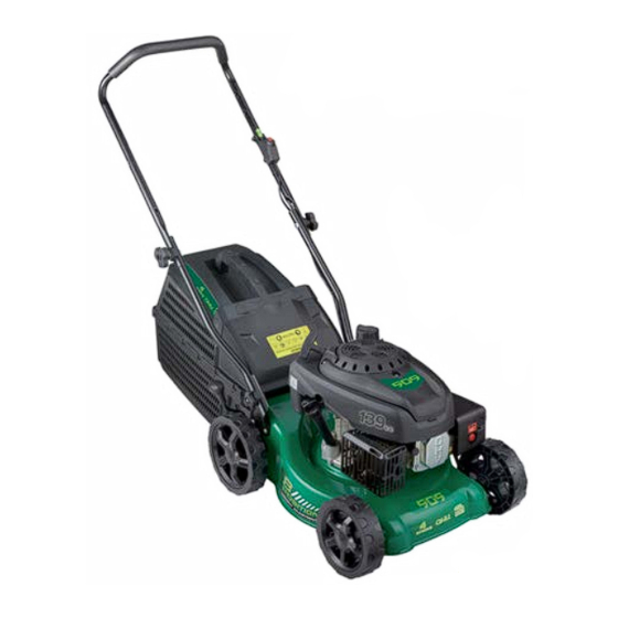
Sfoglia online o scarica il pdf Manuale d'uso per Tagliaerba 909 50620. 909 50620 19. 139cc 4 stroke petrol lawn mower

Assembly
Assembly
WARNING: Stop the engine and unplug the spark plug before any
repairs or maintenance operations.
WARNING: DO NOT attempt to start this mower without first adding
0.6L of SAE 10W/30 engine oil to the Engine.
WARNING: Do Not attempt to start this mower without the mower
first being FULLY assembled.
It is necessary to fit the lower handles (6), upper handle bar and handles (1),
and 45L hard catcher (7) to the mower.
Attaching the Handles
1. To attach the lower handles (6), first remove the two lower handle locking
knobs (8). Place the lower handle in position by aligning the 2 lower
handle ends on the inner side of the lower handle mounting plates (9)
located at the back of the mower deck. (Fig A)
2. Once in position, insert the bolt on each side through the lower handle
(6) and then through the lower handle mounting plate (9).
Orientate the bolt so the head sits correctly in the depression in the
handle tube. (Fig B)
3. Once the bolts are loosely in position, fit the plastic curved washer over
the end of the bolt. Then screw the lower handle bar locking knob (8)
over the plastic curved washer and secure by turning clockwise until tight
and secure. (Fig C)
A.
B.
14
e-mail: [email protected]
MODEL: №. 50620
139cc 4 Stroke Petrol Lawn Mower
C.
LOOSEN
TIGHTEN
AFTER SALES SUPPORT
1800 909 909
(toll free)
139cc 4 Stroke Petrol Lawn Mower
4. After securing the lower handles in to position, extend the upper handle
bar into the upright position, (Fig D) and then simply secure the upper
handle locking knobs (5) that are already loosely in position. (Fig E)
5. Check the on/off switch cable (3) is correctly routed and secured with the
supplied cable clip (4). (Fig F)
WARNING. When opening up the upper handle bar take care NOT
to pinch the switch cable in the hinging of the handle bars and
ensure the cable is not trapped within the bars being clamped.
D.
E.
Assembly of the 45L Hard Catcher
WARNING. Ensure the motor is off and
not operating when undertaking this task.
1. The 45L hard catcher (7) is supplied in two
sections. Locate the top half on top of the
bottom half and interlock them together by
aligning the lugs and slots, and pushing the
halves together until they click into place. (Fig G)
AFTER SALES SUPPORT
1800 909 909
(toll free)
Assembly
F.
LOOSEN
TIGHTEN
G.
e-mail: [email protected]
MODEL: №. 50620
15
