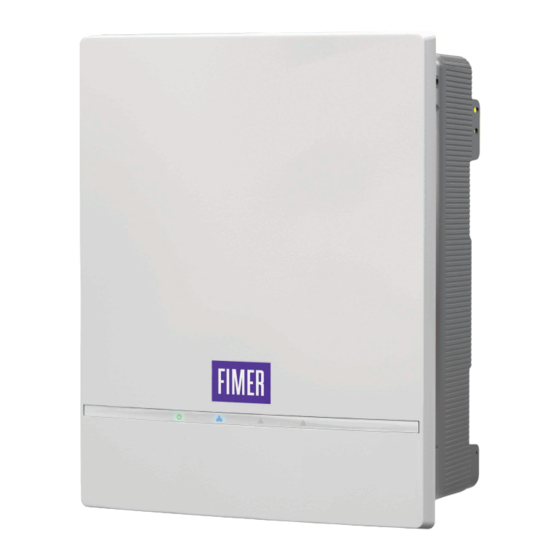
Fimer PVS-10-TL-SY SPD1+2 Manuale di installazione rapida - Pagina 3
Sfoglia online o scarica il pdf Manuale di installazione rapida per Inverter Fimer PVS-10-TL-SY SPD1+2. Fimer PVS-10-TL-SY SPD1+2 8. Solar inverter

2. Labels and Symbols
The labels on the inverter show the conformity marking, main technical
data and identification of the equipment and manufacturer.
NOTE –
The below labels are intended as an example only.
D
Regulatory and
identification Label
A
Made in Italy
DIN VDE
V
V 0126-1-1
SOLAR INVERTER
PROTECTIVE CLASS: I
MODEL:
B
PVS-XX-TL-YY
V
dc max
C
V
dc Operating Range
V
dc
MPP CH
1
V
dc
MPP CH
2
I
dc max
CH
1
I
dc max
CH
2
I
sc max (
CH CH
1/
2)
V
acr
f
r
S
max
P
φ
acr (cos = 1)
P
acr (cos = ± 0.9)
φ
A
φ
dj cos
I
ac max
D
E
IP65
-XX to +XX °C
-XX to +XX °F
F
XX minutes
PN: PPPPPPPPPPP
WO:XXXXXXXXXXXX
G
SO: SXXXXXXXX
SN:YYWWSSSSSS
I
H
QXX
wk: WWYY
J
Fimer S.p.A.
Via Tortona, 25 – I 20144 Milano (MI)
Communication
identification label
WLAN MAC: XX:XX:XX:XX:XX:XX
ETH1 MAC: XX:XX:XX:XX:XX:XX
ETH2 MAC: XX:XX:XX:XX:XX:XX
M
1.
Remove and apply
on the Quick
Installation Guide
SN Inverter: YYWWSSSSSS
PK: 0000-0000-0000-0000
ATTENTION –
The labels placed on the equipment absolutely
A
MUST NOT be removed, damaged, dirtied, hidden, etc.
In the manual and/or in some cases on the equipment, the danger or
caution areas are indicated with signs, labels, symbols, icons.
Simbol
Descriprion
Always refer to instruction manual
General warning - Important safety information
Dangerous voltage
Hot surfaces
Protection rating of equipment
Temperature range
Without insulation transformer
Direct and alternating current, respectively
Positive and negative pole of the input voltage (DC)
Obligation to use protective clothing and/or personal
protective equipment
Point of connection of the protective ground
Risk of electric shock.The discharge time (quantified in the
figure by the number XX) of the stored energy after de-
energizing of the Inverter from both DC side and AC side.
A
Certification marks
B
Inverter model
C
Main technical data
D
IP protection rating
E
Operating temperature range
F
Discharge time
G
Inverter Part Number
Serial Number
• Inverter access point SSID:
FIMER-YYWWSSSSSS
H
• "Host
Name":
YYWWSSSSSS.local
• It is required to register the
inverter in Aurora Vision.
Production date: WWYY where:
I
WW (week) YY (year)
J
Manufacturer
WLAN (Wi-Fi) and ETH1/ETH2
L
(Ethernet) MAC addresses
Product Key. To be used:
• as wireless access point
password
• to access to the Web UI as
M
username and password in
case of lost credentials
• to commission inverter using
FIMER "Installer for Solar
Inverters" APP.
QR Code:
L
To be used to commission
H
N
inverter, using FIMER "Installer
for Solar Inverters" app, for
claiming process.
N
3. Lifting and transporting
Transportation and relocation
The transportation of the device, in particular via land transportation, must
be made with adequate means and ways to protect the parts from violent
impacts, humidity, vibrations, etc.
ATTENTION –
A
maximum load of 5 stacked pallet (2 units each pallet).
Lifting
The means used for lifting must be
suitable to bear the weight of the
equipment.
Weight of the equipment
Model
All models
http://FIMER-
Unpacking and inspection
The packaging components must be removed and disposed according
to the applicable regulations of the country where the device is installed.
Upon opening the packaging, check the integrity of the equipment and
verify that all the components are present.
If you notice defects or deterioration, stop the operations and call the
carrier, as well as inform FIMER Service immediately.
Please keep the packaging in the event it has to be returned; the use of
inadequate packaging will void the warranty.
Always store the Quick Installation Guide, all the supplied accessories in
a safe place.
4. Installation planning
General recommendation on installation position
• Refer to Technical data table to check the required environmental
conditions (protection rating, temperature, humidity, altitude, etc.).
• The installation location shall be easily accessible.
• Installation of the unit in a location exposed to direct sunlight is NOT
acceptable. (Add awning in case of direct sunlight installation).
• Final installation of the device must not compromise access to any
disconnection devices that may be located externally.
• Do not install in small closed rooms where air cannot circulate freely.
• Always ensure that the flow of air around the inverter is not blocked so as
to prevent overheating.
• Do not install in locations where flammable substances or gases may be
present (minimum distance 3 m).
• Do not install on wooden walls or other flammable supports.
• Install on a wall or strong structure suitable to bear the weight.
• Do not install in rooms where people live or where the prolonged
presence of people or animals is expected, because of the high noise that
the inverter produces during operation. The level of the sound emission
is heavily influenced by where the appliance is installed (for example: the
type of surface around the inverter, the general properties of the room,
etc.) and the quality of the electricity supply.
• All installations over 6561 ft (2,000 meters) must be valued taking in
consideration the derating reported in the datasheet.
Tilting admittance
The unit can be installed in vertical with a maximum inclination as indicated
in the figures below.
5° MAX
If the package is stored correctly, it can withstand a
Weight
29.6 Kg / 65lb
5° MAX
3
