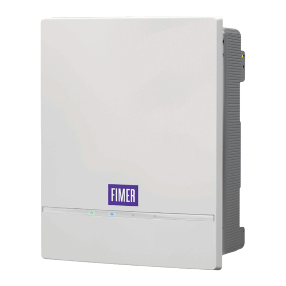
Fimer PVS-10-TL-SY SPD1+2 Manuale di installazione rapida - Pagina 5
Sfoglia online o scarica il pdf Manuale di installazione rapida per Inverter Fimer PVS-10-TL-SY SPD1+2. Fimer PVS-10-TL-SY SPD1+2 8. Solar inverter

Assembly the Inverter to the bracket
ATTENTION –
It is recommended to use the handles (that have to
A
be ordered separately) to handle and safety install the inverter.
ATTENTION –
Risk of injury due to the heavy weight of the
A
equipment. Always consider the center of gravity of the enclosures
while lifting.
• Lift the inverter up to
the bracket (05) (using
the handles (25) or M8
eyebolts) and insert the
two sides anchor points
(placed on sides of
the wall bracket) into
the two slots on the
inverter. Check that the
anchor points has been
correctly inserted in the
slots before releasing
the inverter.
• Remove the handles (25) or eyebolts and tighten the supplied two side
bracket screws (18) (Tightening torques 3.5 Nm) to avoid the tilting of the
bottom part of the inverter.
• A padlock can be installed to lock the inverter to the bracket so that it
cannot be disassembled by outsiders.
18
• Remove
the
protective
wireless antenna located on the bottom side of the inverter.
Install the wireless antenna by screwing it into the specific connector (14).
7. AC grid output connection
7.1 Characteristics and sizing of the protective
grounding cable
ATTENTION –
Any failure of the inverter when it is not connected
A
to earth through the appropriate connection point is not covered by
the warranty.
The earth connection can be made:
• On the Protective Earth (PE) external connection point (04).
WARNING –
The cross section of the protective earthing conductor
B
must have same cross section as the phases cables and its minimum
must be 10 mm
(Copper wire).
2
• On both Protective Earth (PE) external connection point (04) and on the
AC quick fit connector (09) using cables having same cross section as
the phases cables.
ATTENTION –
Installation of a second protective earth cable is also
A
required by regulations in force in certain countries of installation.
cover
from
the
connector
7.2 Characteristics and sizing of the line cable
The AC cables must be connected to the AC output connector (17) using
the specific AC quick fit connector (09) supplied.
AC conductor cable
Cable diameter
range
Conductor
cross
section
Conductor material
7.3 Protection switch under load (AC switch) and
differential protection
To protect the AC connection line of the inverter, it is recommended to
install a protection device against overcurrent and earth leakages with the
following features:
Load protection breaker PVS-10-TL
Type
Voltage/current rating
Magnetic protection
05
Number of poles
25
Differential protection type A/AC
Differential sensitivity
(*): please consider thermal and other derating when selecting the current
rating of the protection equipment for your application.
7.4 Connection on the Protective earth (PE) cable
• Strip the cable.
• Install the supplied M6 cable lug on
the earth cable.
• Install the earth wire on the
Protective earth (PE) external
connection point (04) following the
installation sequence (Tightening
torque 4 Nm):
- Serrated washer
- Earth cable
- Serrated washer
- M6 screw
of
the
7.5 AC output cables connection
ATTENTION –
A
external AC switch downstream to the inverter (grid side) is in OFF
position applying LOTO procedure on it.
The connection of the AC cable must be made on the AC output connector
(17), located on the bottom side of the inverter, using the AC quick fit
connector (09).
• Unscrew the AC cable
gland (23) installed on
the AC quick fit connector
(09).
• Remove the internal screw
terminal block.
Press the 2 retain clips and
pull out the screw terminal
block.
ATTENTION –
A
that can be used in combination to accept a 11...26mm diameter cable.
- Cable diameter 11...19mm. Default configuration (both gasket installed).
- Cable diameter 19...26mm. Remove the reducing clamping range gasket.
• 11...19 mm or 19...26mm based on the type of
seals installed
• 6mm
...16mm
(with plastic collar ferrule)
2
2
accepted by the AC quick fit connector.
copper
PVS-12.5-TL PVS-15-TL
Automatic circuit breaker with thermal-
magnetic protection
400Vac
400Vac
min25A (*)
min32A (*)
Magnetic curve B/C
3W (3 phases without neutral wire) or
4W (3 phases with neutral wire).
300 mA
Before carrying out any operation, check that any
On the connector cable gland 2 gasket are installed
400Vac
min32A (*)
5
