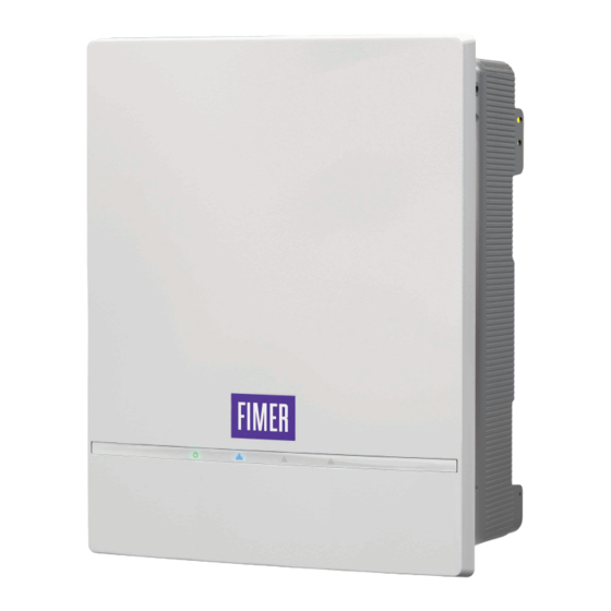
Fimer PVS-10-TL-SY SPD1+2 Manuale di installazione rapida - Pagina 7
Sfoglia online o scarica il pdf Manuale di installazione rapida per Inverter Fimer PVS-10-TL-SY SPD1+2. Fimer PVS-10-TL-SY SPD1+2 8. Solar inverter

ATTENTION –
Refer to document "String inverters - Product
A
manual appendix" available at
manufacturer and model of quick fit connector used on the inverter.
Click
Click
ATTENTION –
Check that protective caps are installed on unused
A
connectors. This is necessary for the inverter seal and to avoid any
damage to the unused connectors which may be used at a later time.
ATTENTION –
The quick fit connectors must be properly installed.
A
After the installation make sure the connectors are correctly locked
through the clips.
9. Instruments
The synoptic (03) allows to view inverter status conditions to be analyzed
in greater depth by consulting the manual.
POWER
Solid when the inverter is working correctly. Flashes when
checking the grid or if there is insufficient sunlight.
WLAN
Indicates the status of the Wi-Fi or Ethernet communication lines.
ALARM
The inverter has detected an anomaly. The anomaly is shown
on the "EVENTS" section of the internal webserver.
GFI
Ground fault on the DC side of the PV generator. The error
is shown on the "EVENTS" section of the internal webserver.
NOTE –
The icons, in various combinations, can indicate multiple
D
conditions other than the original single condition; see the various
descriptions on the product manual.
10. Commissioning
The inverter can be commissioned in a simple and intuitive way through
the Installer for solar inverters APP for mobile devices.
NOTE –
The same configurations can be done via internal web
D
User Interface (see product manual).
• Supply the inverter with DC input voltage from the photovoltaic generator
and via AC grid voltage.
ATTENTION –
The inverter configuration can be also performed
A
with only one supply source (DC or AC).
ATTENTION –
With DC supply, make sure that the irradiation is
A
stable and adequate for the inverter commissioning procedure to be
completed.
• Open the " Installer for solar inverters" APP.
• Login or Sign-In to Aurora vision account.
• Tap on "Commissioning wizard". A QR code scanner will be opened.
www.fimer.com
to find out the
• Scan
the
QR
code
Communication identification label and
connect to inverter network.
NOTE –
The name of the Wi-Fi
D
network created by the inverter will
be: FIMER-YYWWSSSSSS (10
digit Inverter SN).
NOTE –
After this step wait 10 seconds to allow the Wi-Fi connection
D
Once connected, the commissioning wizard will start.
10.1 COMMISSIONING WIZARD
10.1.1 Network configuration.
• Choose the connection type (ethernet or wireless) and set the related
parameters.
NOTE –
This step can be skipped and performed later (via WebUI).
D
• Once network parameters were setted, tap on "Next".
10.1.2 Date and Time.
• Set the Date, Time and Time zone
(The inverter will propose these fields if
connected to internet).
• Once date and time were setted, tap on
"Next".
10.1.3 Inverter configuration.
Country standard
• Set the grid standard of the country
in which the inverter is installed.
Some Country standards have different
grid voltage that should be setted during
this step.
• Confirm the settings by clicking "Save".
The configuration wizard is complete
and the inverter will reboot.
• If the outcome of the preliminary checks on the grid parallel is positive, the
inverter connects to the grid and starts to export power to the grid. The
"Power" LED remains fixed on while the "Alarm" and "GFI" LEDs are off.
NOTE –
To address any problems that may occur during the
D
initial stages of operation of the system and to ensure the inverter
remains fully functional, you are advised to check for any firmware
updates in the download area of the website www.fimer.com or at
https://registration.solar.fimer.com (instructions for registering on the
website and updating the firmware are given in the product manual).
WLAN MAC: XX:XX:XX:XX:XX:XX
ETH1 MAC: XX:XX:XX:XX:XX:XX
on
the
ETH2 MAC: XX:XX:XX:XX:XX:XX
1.
Remove and apply
on the Quick
Installation Guide
SN Inverter: YYWWSSSSSS
PK: 0000-0000-0000-0000
7
